
Access Router Device, Mobility Control System, and Mobility Control Method

a technology of mobility control system and access router, which is applied in the direction of wireless network protocols, electrical equipment, wireless commuication services, etc., can solve the problems of route redundancy, mobile terminal devices which support only mip cannot perform the function of hmip in a network where hmip has been deployed, and mobile terminal devices which have no function of hmip cannot enjoy the effect of delay time reduction

Inactive Publication Date: 2009-02-19
NTT DOCOMO INC
View PDF7 Cites 8 Cited by
  • Summary
  • Abstract
  • Description
  • Claims
  • Application Information

AI Technical Summary

Benefits of technology

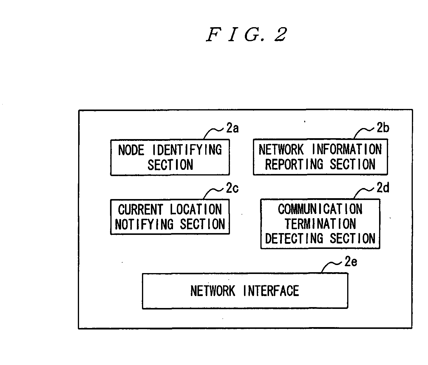
[0012]An access router device according to claim 2 of the present invention is the access router device according to claim 1 characterized in that it further comprises communication termination detecting means for detecting a communication termination of the mobile terminal device, wherein the network information reporting means reports network information to be originally notified to the mobile terminal device if the mobile termination detecting means detects the communication termination. Thereby, an appropriate mobility control node can be selected to change a subsequent communication route after the communication termination so that increase of delay time in packet forwarding can be prevented.
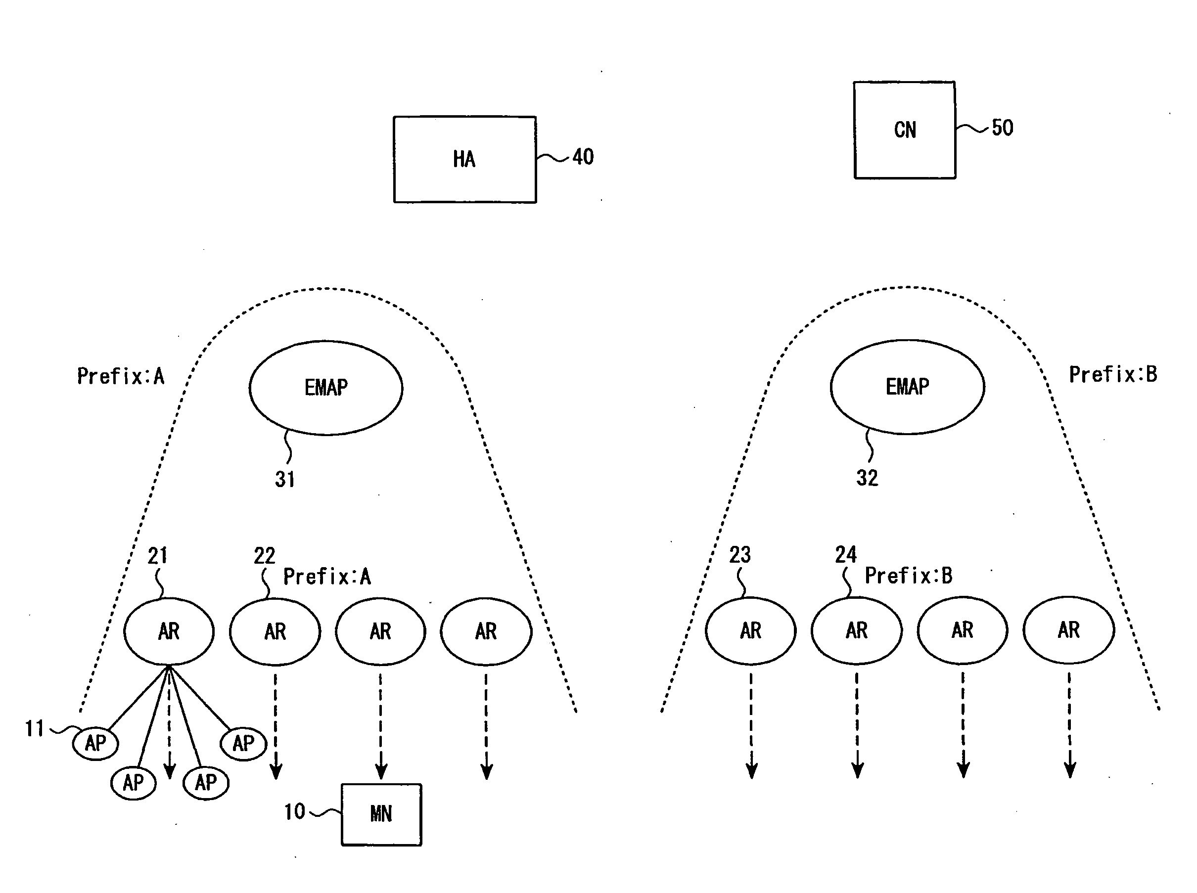
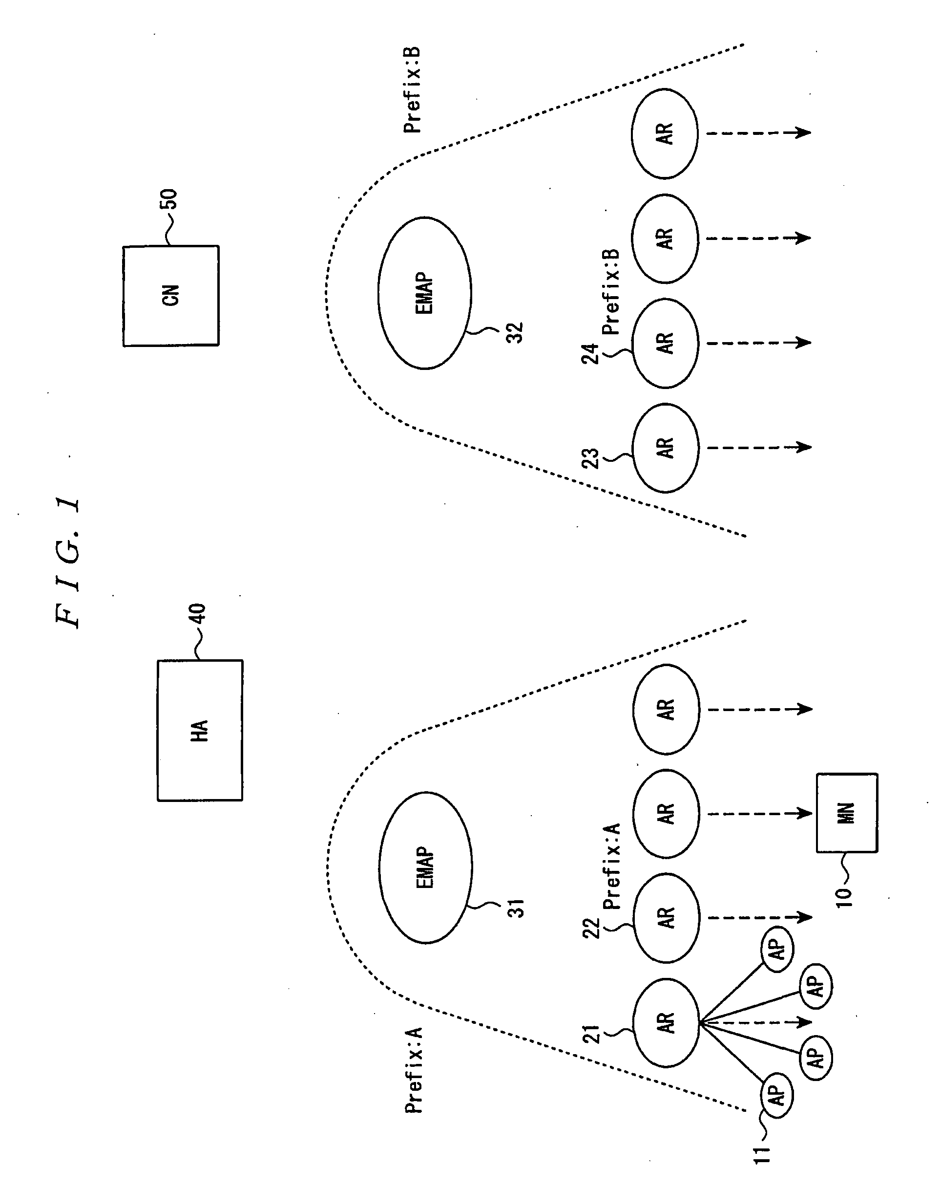
[0020]the mobility control node which receives the notification notifies the mobility control node corresponding to the local network of the mobile terminal device before the movement of the own node as a current location of the mobile terminal device. This is a configuration for implementing processing of FIG. 6 described later, and can reduce position registering time more than in the case of FIG. 5.
[0024]a node identifying step of identifying a mobility control node corresponding to a local network of the mobile terminal device before the movement if the mobile terminal device moves into the area, a network information reporting step of reporting network information used in the local network corresponding to the mobility control node identified by the node identifying step to the mobile terminal device, a notifying step of notifying the mobility control node corresponding to a local network of a destination to which the mobile terminal device moves of an access router device corresponding to the area as a current location of the mobile terminal device, and a notifying step of notifying the mobility control node corresponding to the local network of the mobile terminal device before the movement of information about the mobility control node of the destination as a current location of the mobile terminal device. This is a configuration for implementing processing of FIG. 6 described later, and can reduce position registering time more than in the case of FIG. 5.
[0025]As described above, the present invention can achieve movement across local networks formed by mobility control nodes without adding a function to a mobile terminal device. In addition, by selecting an optimum mobility control node after the communication termination and performing a route change procedure, a route can be changed without regard to deterioration of communication quality. Thereby, when starting communication, the mobile terminal device can always start the communication using an optimum mobility control node.

Problems solved by technology

Therefore, a mobile terminal device which has no function of HMIP cannot enjoy the effect of delay time reduction due to placing an MAP.
Therefore, a mobile terminal device which supports only MIP cannot perform the function of HMIP in a network where HMIP has been deployed.
Therefore, it is concerned that a route becomes redundant if a mobile terminal device moves while continuing communication.
However, since this requires complicated control, the problem of reduction of HO processing capacity is caused by increase of the number of control message transmitted within wireless and wired zones and delay time associated with complexity of the control.

Method used


Image

  • Access Router Device, Mobility Control System, and Mobility Control Method
  • Access Router Device, Mobility Control System, and Mobility Control Method
  • Access Router Device, Mobility Control System, and Mobility Control Method

Examples


modification examples

(Other Modification Examples)

[0092]Although MIP is given as an example of a packet transfer protocol from the CN 50 to an EMAP in the foregoing description, the scheme thereof is not limited to MIP and can be applied to various protocols which enable mobility on an IP network.

[0093]In addition, although the foregoing description is based on the address generation procedure of IPv6 stateless, the present invention can also be applied to an address generation procedure of stateful using DHCP or the like. Specifically, in DHCP, a confirm message is sent to a network to confirm validity of an address when the MN 10 moves. With this response, the MN 10 determines that the same address can be continually used even after the movement.

[0094]Then, when the MN 10 moves across local networks, the MN 10 sends a confirm message to an AR. Upon receiving this, the AR extracts a terminal identifier from the message, and determines that the MN 10 has moved from a local network formed by an EMAP that...


PUM


Abstract

In a network configuration in which a mobility control node is placed in the network, a packet is forwarded from a communication partner to the mobility control node by a basic IP mobility protocol for supporting movement in a local network managed by the mobility control node, a movement of a mobile terminal device across local networks formed by mobility control nodes is achieved without adding a function to the mobile terminal device. A mobility control node to be provided to the mobile terminal device is identified by a trigger reporting a movement has been performed to the network from the mobile terminal device, and, in the case of HO across between mobility control nodes, network information before the movement is reported instead of network information to be originally reported. Thus, the mobile terminal device determines that the movement is in the same network and can continue communication without performing an address generation procedure.

Description

TECHNICAL FIELD[0001]The present invention relates to an access router device, a mobility control system, and a mobility control method, and particularly to an access router device, a mobility control system, and a mobility control method that are used in a network configured in a way that a mobility control node is placed in the network, a packet is forwarded from a communication partner to the mobility control node by a basic IP mobility protocol for supporting movement in a local network managed by the mobility control node.BACKGROUND ART[0002]As a technique for supporting mobility in an IP network, Mobile IPv6 (MIP) has been proposed by IETF (Internet Engineering Task Force) (see Non-Patent Document 1). MIP allows a communication to continue even if a mobile terminal device moves by placing a mobility control node called Home Agent in a network and managing a position of the mobile terminal device in this node. As a technique for improving performance of handover (hereinafter ab...

Claims


Application Information

Patent Timeline
IPC IPC(8): H04W8/02H04W8/08H04W36/00H04W36/08H04W36/38H04W40/24H04W80/04H04W88/00
CPCH04W8/087H04W36/0011H04W88/005H04W80/04H04W40/24H04W36/0019
Inventor ISOBE, SHIN-ICHINISHIDA, KATSUTOSHIMATSUBARA, NAOKI
Owner NTT DOCOMO INC
Learn More