
Reliability System for Use with Non-Volatile Memory Devices

a non-volatile memory and reliability system technology, applied in static storage, digital storage, instruments, etc., can solve problems such as data integrity may be at risk, device to enter a crisis reliability mode of operation, device to reduce user data space within the flash memory device, etc., to reduce user data space, reduce data integrity risk, and increase spare block space

Inactive Publication Date: 2009-02-19
DELL PROD LP
View PDF16 Cites 29 Cited by
  • Summary
  • Abstract
  • Description
  • Claims
  • Application Information

AI Technical Summary

Benefits of technology

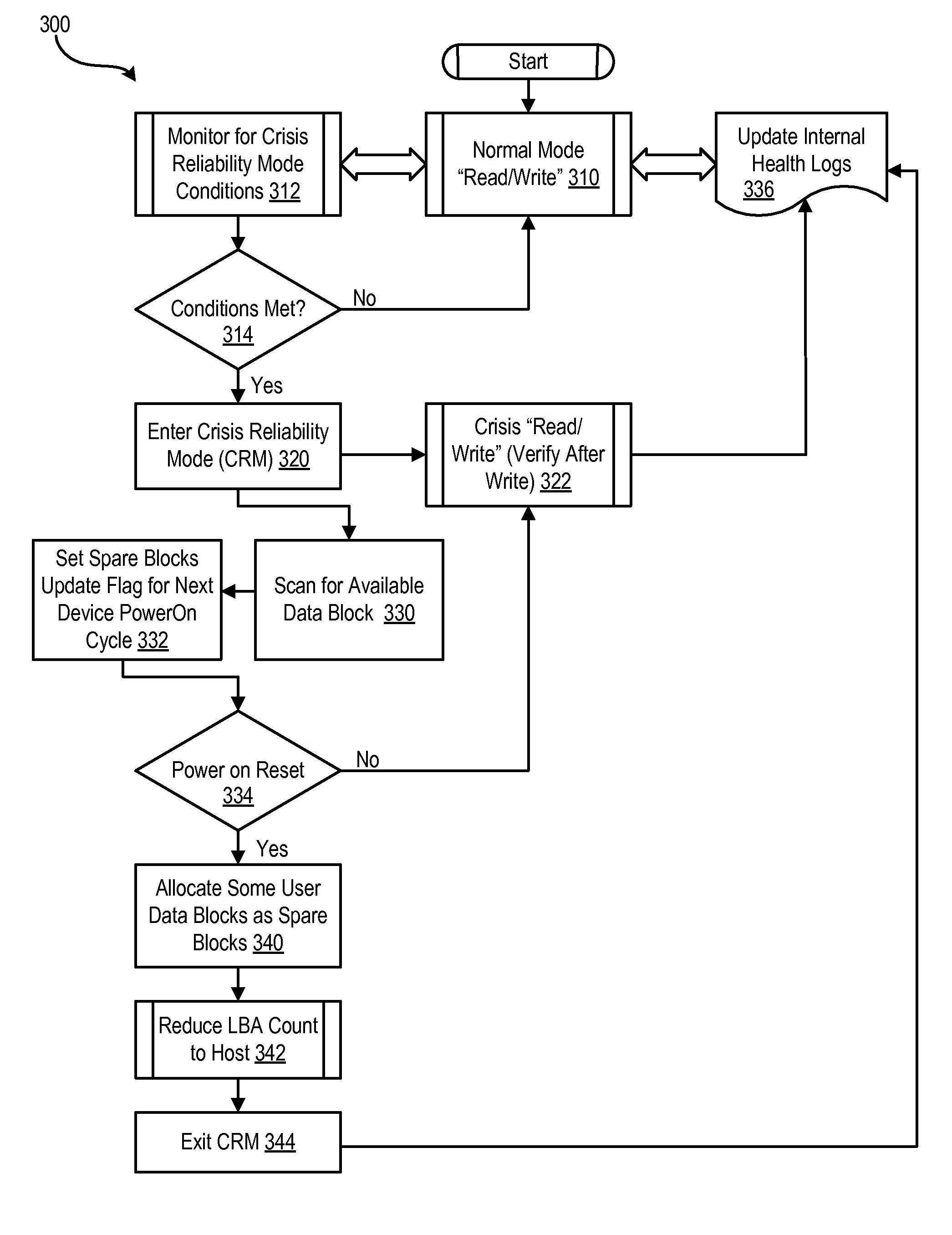
[0011]In certain embodiments, the crisis reliability mode module monitors any of these conditions and, if true, causes the device to enter a crisis reliability mode of operation. During the crisis reliability mode of operation, the device scans for available user data blocks that can be used as extra spare blocks and then sets a flag for an LBA counter change. The LBA counter change flag initiates the process of reallocation of blocks for the next device power on cycle. Thus during the next power on cycle, the device reduces the user data space within the flash memory device and increases the spare block space. After the device has been restored to a healthy level of spare blocks, the flash memory management system returns to a normal operational mode with low risk to data integrity. The reliability improvement module can be implemented within software so that no change to device hardware is necessary.

Problems solved by technology

The crisis reliability mode of operation is declared when the memory management system determines that it may not guarantee the data integrity of data stored within a corresponding flash memory.
Data integrity may be at risk for such reasons as a low number of reserved spare blocks, a high number of erase and program cycles that may exceed or approach a device's capability or a high level of error correction code (ECC) correction of data or error detection code (EDC) detected errors for data that is read from the flash memory.
In certain embodiments, the crisis reliability mode module monitors any of these conditions and, if true, causes the device to enter a crisis reliability mode of operation.
Thus during the next power on cycle, the device reduces the user data space within the flash memory device and increases the spare block space.

Method used


Image

  • Reliability System for Use with Non-Volatile Memory Devices
  • Reliability System for Use with Non-Volatile Memory Devices
  • Reliability System for Use with Non-Volatile Memory Devices

Examples


Embodiment Construction

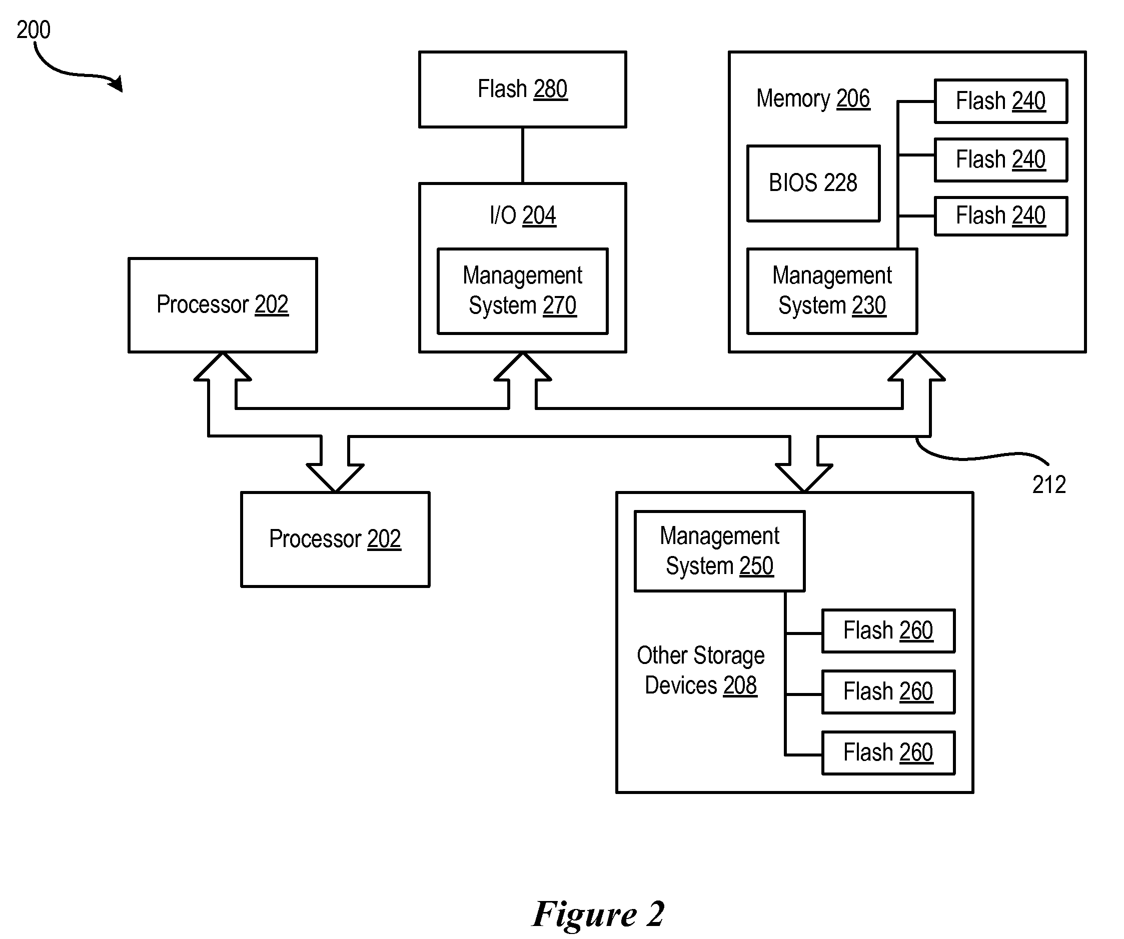
[0019]FIG. 2 shows a block diagram of an information handing system 200 which includes a flash memory management system in accordance with the present invention. The information handling system 200 includes a processor 202, input / output (I / O) devices 204, such as a display, a keyboard, a mouse, and associated controllers, memory 206 including non-volatile memory such as a hard disk drive and volatile memory such as random access memory, and other storage devices 208, such as an optical disk and drive and other memory devices, and various other subsystems 210, all interconnected via one or more buses, shown collectively as bus 212. The memory 206 includes a basic input output system 228 which is executed by the processor.

[0020]The information handing system also includes one or more flash memory devices and corresponding flash memory management systems. For example, the memory 206 can include a flash memory management system 230 as well as one or more flash memory modules 240. The ot...


PUM


Abstract

A system and method which provides a non-volatile memory management system with the ability to monitor the health of a corresponding non-volatile memory and to safeguard data stored within the non-volatile memory when data integrity is at risk. The monitoring and safeguarding is provided via a crisis reliability mode module which monitors the health of a corresponding non-volatile memory and to enters a crisis reliability mode of operation when data integrity within the non-volatile memory is at risk.

Description

BACKGROUND OF THE INVENTION[0001]1. Field of the Invention[0002]The present invention relates to the field of information handling systems and more particularly to non-volatile memory used with information handing systems.[0003]2. Description of the Related Art[0004]As the value and use of information continues to increase, individuals and businesses seek additional ways to process and store information. One option available to users is information handling systems. An information handling system generally processes, compiles, stores, and / or communicates information or data for business, personal, or other purposes thereby allowing users to take advantage of the value of the information. Because technology and information handling needs and requirements vary between different users or applications, information handling systems may also vary regarding what information is handled, how the information is handled, how much information is processed, stored, or communicated, and how quick...

Claims


Application Information

Patent Timeline
Patent Type & Authority Applications(United States)
IPC IPC(8): G11C11/34
CPCG11C16/22
Inventor HALLOUSH, MUNIF FARHANPRATT, THOMAS L.
Owner DELL PROD LP
Learn More