
Nonvolatile memory device

a memory device and non-volatile technology, applied in semiconductor devices, digital storage, instruments, etc., can solve the problems of long time required for rewriting and the restriction of attaining higher speed, and achieve the effect of reducing resistance, high reliability, and suppressing the occurrence of corruptive routines

Active Publication Date: 2009-02-19
PANASONIC CORP
View PDF9 Cites 25 Cited by
  • Summary
  • Abstract
  • Description
  • Claims
  • Application Information

AI Technical Summary

Benefits of technology

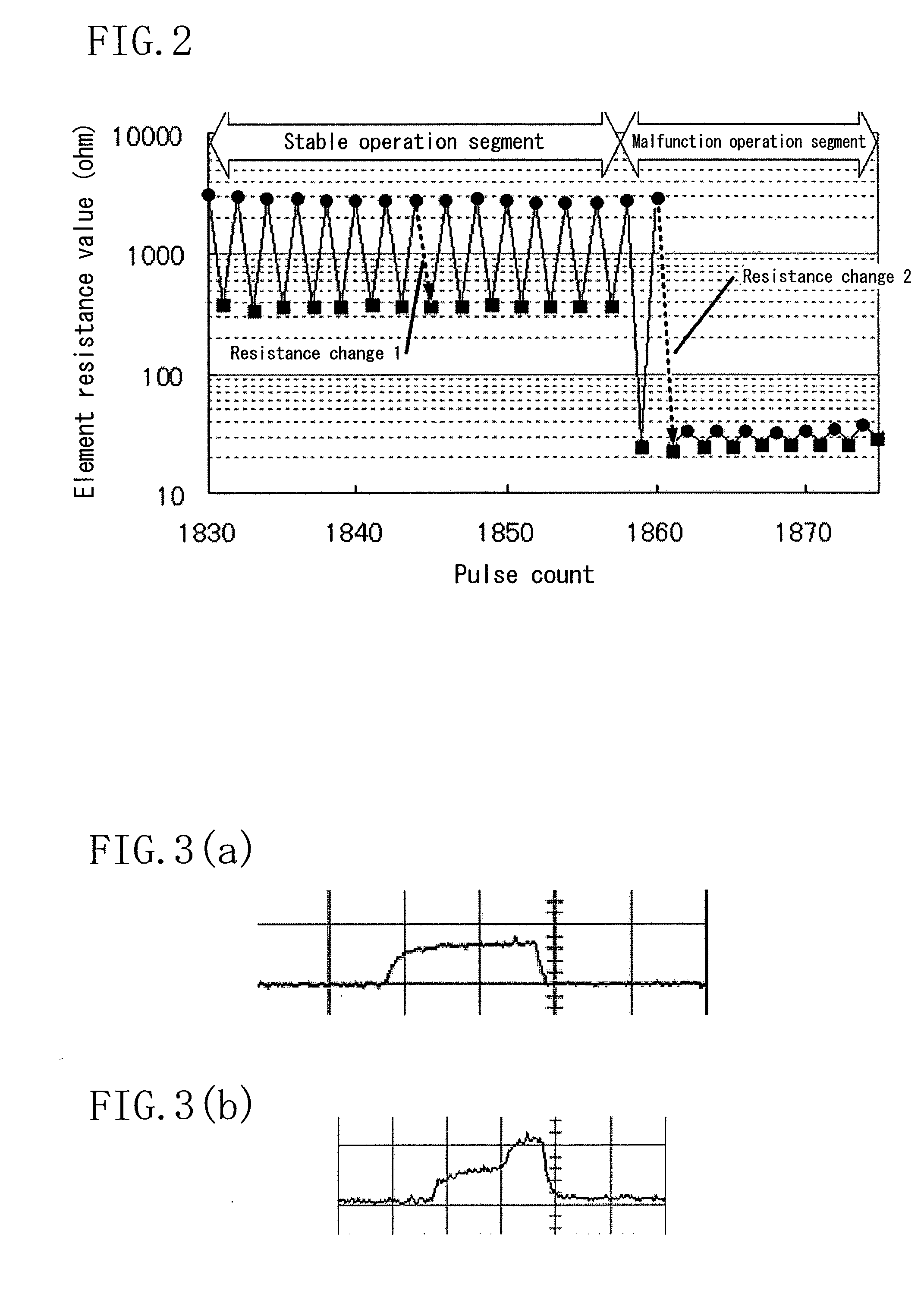
[0022]As described above, according to the present invention, by providing the erase pulse limiting fixed resistance element and the erase pulse limiting variable resistance element, it is possible to suppress occurrence of a corruptive routine in which, in applying a predetermined voltage pulse to a variable resistance element (e.g., a RRAM element) whose resistance value changes under electrical stimulation in a direction of decrease of the resistance (low resistance state), in particular, a large amount of current may flow as the element resistance decreases, and resultant further decrease in element resistance may cause flow of a large amount of current, causing further decrease in resistance. Hence, a nonvolatile memory device with extremely high reliability that maintains stable resistance change can be provided.

Problems solved by technology

The flash memory, structured to accumulate charge at a floating gate in a high electric field, is so complicated in cell structure that many problems arise in attainment of higher integration.
A very long time is therefore required for rewrite and attainment of higher speed is restricted.

Method used


Image

  • Nonvolatile memory device
  • Nonvolatile memory device
  • Nonvolatile memory device

Examples


embodiment 1

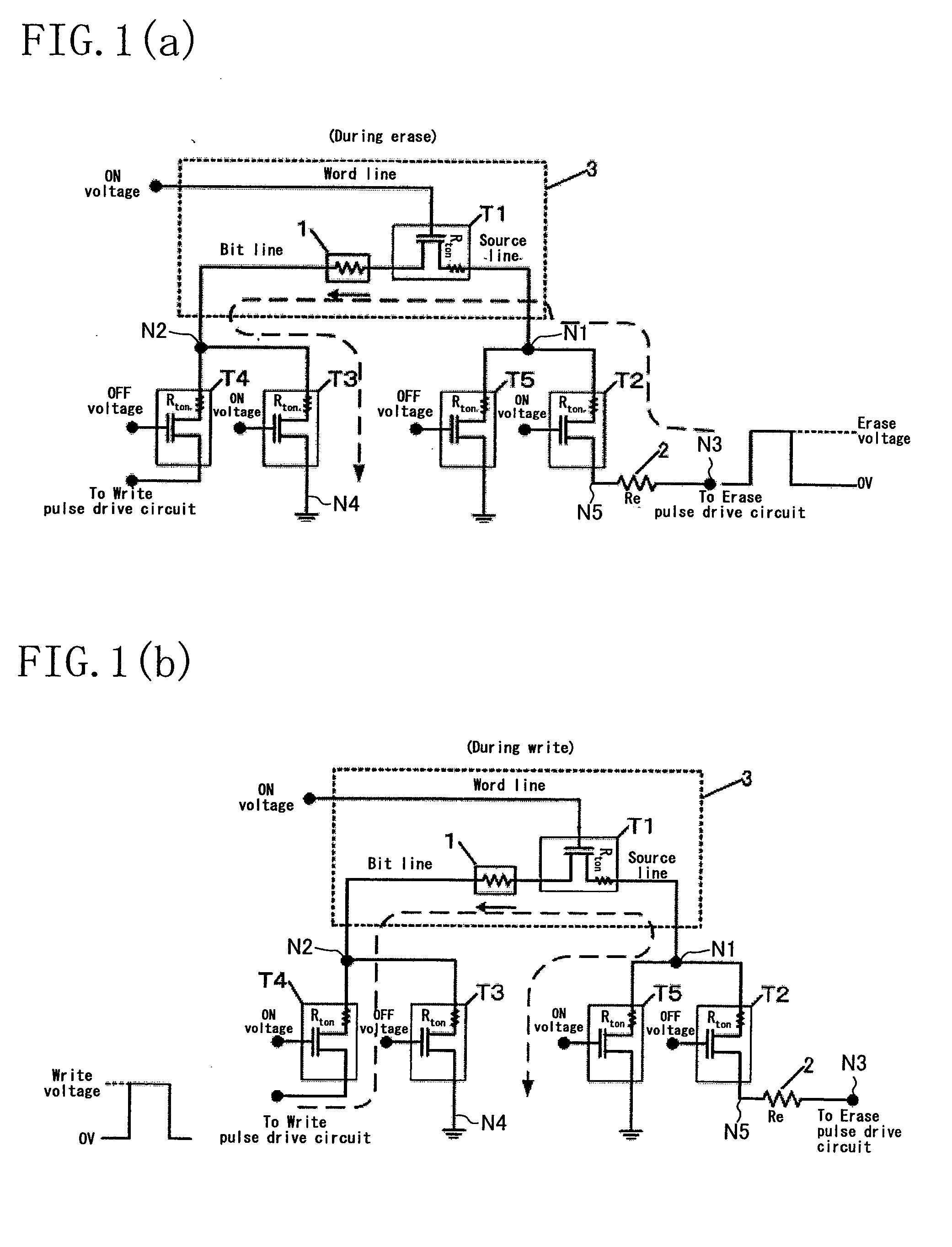
[0048]FIG. 1 shows a configuration of a memory cell of an inventive device together with configurations of drive circuits in the states of applying an erase pulse and a write pulse to the memory cell. Note that the erase pulse as used herein is defined as a pulse that changes a variable resistance element from high resistance to low resistance, in which the pulse width and the voltage amplitude are predetermined values. Note also that the write pulse as used herein is defined as a pulse that, in reverse to the erase pulse, changes a variable resistance element from low resistance to high resistance, in which, similarly to the above, the pulse width and the voltage amplitude are predetermined values corresponding to the element.

[0049]As shown in FIGS. 1(a) and 1(b), the nonvolatile memory device of this embodiment includes a memory cell 3, selection transistors T2 to T5 and an erase pulse limiting fixed resistance 2.

[0050]The memory cell 3 includes a variable resistance element 1 and...

embodiment 2

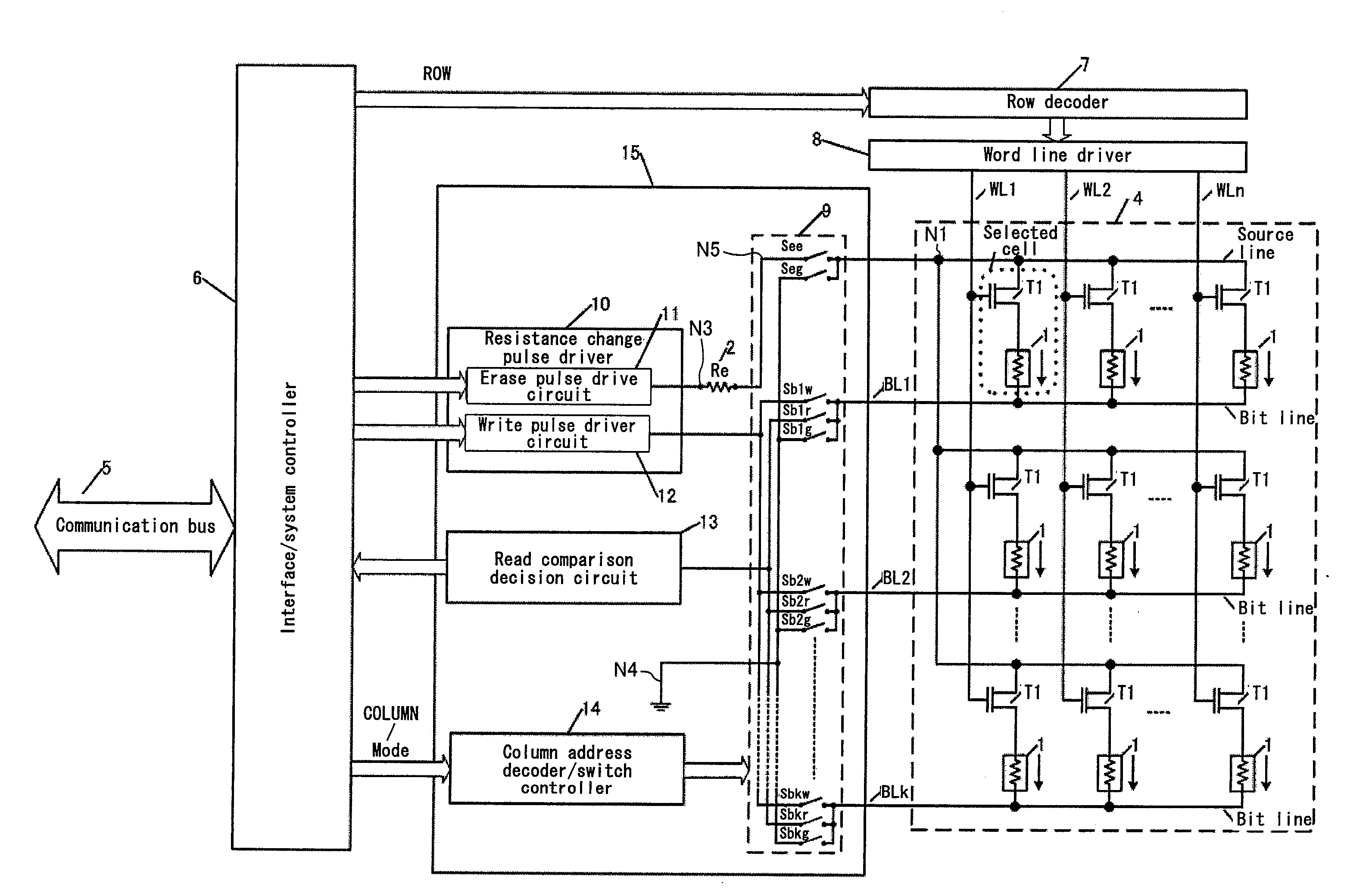
[0063]The inventive device of Embodiment 2 will be described with reference to the relevant drawing. FIG. 7 is a block diagram of a nonvolatile memory device of this embodiment. In FIG. 7, a memory cell array 4 includes a plurality of memory cells arranged in a matrix. Each of the memory cells is the memory cell described in Embodiment 1. The same reference numerals as those in FIG. 1 are therefore the same in operation and thus description thereof is omitted here. In the memory cell array 4, the gates of transistors T1 (first selection switch elements) in each row are short-circuited (commonly connected to the corresponding word line WL1, WL2, . . . , WLn). Each bit line for cells in each column is also short-circuited (terminals of variable resistance elements 1 in each column are commonly connected to the corresponding bit line BL1, BL2, . . . , BLk via second nodes). Moreover, all source lines for all cells are short-circuited (terminals of transistors T1 of the cells are common...

embodiment 3

[0069]The inventive device of Embodiment 3 will be described with reference to the relevant drawing. FIG. 8 is a block diagram of a nonvolatile memory device of Embodiment 3. In FIG. 8, the same reference numerals as those in FIG. 7 are the same in function and thus description thereof is omitted here. The point different from FIG. 7 is that an erase pulse limiting variable resistance 16 is provided in place of the erase pulse limiting fixed resistance 2. The erase pulse limiting variable resistance 16 can change the resistance value in stages under an instruction from the system controller 6. The internal circuit configuration of the erase pulse limiting variable resistance 16 is not specifically shown, but can be implemented by configuring a resistance array composed of predetermined fixed resistances connected in series and selecting an appropriate number of resistances using transistor switches.

[0070]With the configuration of this embodiment, the following advantage can be obtai...


PUM


Abstract

A variable resistance element (1) whose resistance changes with application of a voltage pulse is brought to a low resistance state by applying an erase pulse to a path shown by the broken line through selection of selection transistors. An erase pulse limiting resistance (2) is inserted in the broken-line path. The resistance value (Re) of the erase pulse limiting resistance (2) is set so that a first resistance value as the sum of all the ON resistance values of the selection transistors, Re and the wiring resistance in the path is equal to or more than a bulk resistance value of a thin film material used in the variable resistance element (1), to prevent the resistance of the variable resistance element (1) from decreasing to the bulk resistance value at which stable resistance change is not resumed.

Description

TECHNICAL FIELD[0001]The present invention relates to a nonvolatile memory having a memory cell permitting electrical data write / erase using a variable resistance element whose electric resistance changes, and more particularly to a nonvolatile memory device including a memory cell array having a plurality of such memory cells.BACKGROUND ART[0002]Nonvolatile memory devices are widely incorporated in portable equipment such as cellular phones and digital cameras, and the uses thereof have rapidly expanded. In recent years, with increase of the occasion of handling audio data and video data, nonvolatile memory devices larger in capacity and operating at higher speed than conventionally attained have come to be demanded intensely. Also, because of their uses in portable equipment, demands for lower power have been further intensified.[0003]Under the background described above, flash memory, which controls charge accumulated at a floating gate to store data, is currently the mainstream ...

Claims


Application Information

Patent Timeline
IPC IPC(8): G11C11/00
CPCG11C11/5685G11C13/0007G11C13/0069G11C2013/009H01L27/2436G11C2213/34G11C2213/79H01L27/101G11C2213/32H10B63/30
Inventor KATOH, YOSHIKAZU
Owner PANASONIC CORP
Learn More