
Synchronizing Timing of Multiple Physically or Logically Separated System Nodes

a technology of synchronizing timing and multiple systems, applied in the field of lithographic equipment, can solve the problems of difficult accurate synchronization of multiple systems, and achieve the effect of effective synchronization of various systems

Inactive Publication Date: 2009-02-19
ASML NETHERLANDS BV
View PDF19 Cites 8 Cited by
  • Summary
  • Abstract
  • Description
  • Claims
  • Application Information

AI Technical Summary

Benefits of technology

[0009]A system and method that is able to effectively synchronize various systems and subsystems in a lithographic apparatus is provided.

Problems solved by technology

Very accurate synchronization of multiple systems is difficult, especially if the parts of the lithographic apparatus are physically installed outside the actual fabrication room.
For maskless systems, this is typically the case due to heat regulation issues, physical constraints and price per square meter in the clean room environment.

Method used


Image

  • Synchronizing Timing of Multiple Physically or Logically Separated System Nodes
  • Synchronizing Timing of Multiple Physically or Logically Separated System Nodes
  • Synchronizing Timing of Multiple Physically or Logically Separated System Nodes

Examples


Embodiment Construction

[0026]This specification discloses one or more embodiments that incorporate the features of this invention. The disclosed embodiment(s) merely exemplify the invention. The scope of the invention is not limited to the disclosed embodiment(s). The invention is defined by the claims appended hereto.

[0027]The embodiment(s) described, and references in the specification to “one embodiment”, “an embodiment”, “an example embodiment”, etc., indicate that the embodiment(s) described may include a particular feature, structure, or characteristic, but every embodiment cannot necessarily include the particular feature, structure, or characteristic. Moreover, such phrases are not necessarily referring to the same embodiment. Further, when a particular feature, structure, or characteristic is described in connection with an embodiment, it is understood that it is within the knowledge of one skilled in the art to effect such feature, structure, or characteristic in connection with other embodiment...


PUM


Abstract

A method for synchronizing a plurality of series coupled nodes is described. A master trigger is transmitted through the plurality of series coupled local nodes in a downstream direction from a first node to a last node and retransmitted through the plurality of series coupled nodes in an upstream direction from the last node to the first node. Then, a local synchronization time is calculated at each of the plurality of series coupled nodes based on a differential measurement between the arrival of the master trigger in the downstream direction and the upstream direction. Operations in the local nodes may be synchronized based on the local synchronization time.

Description

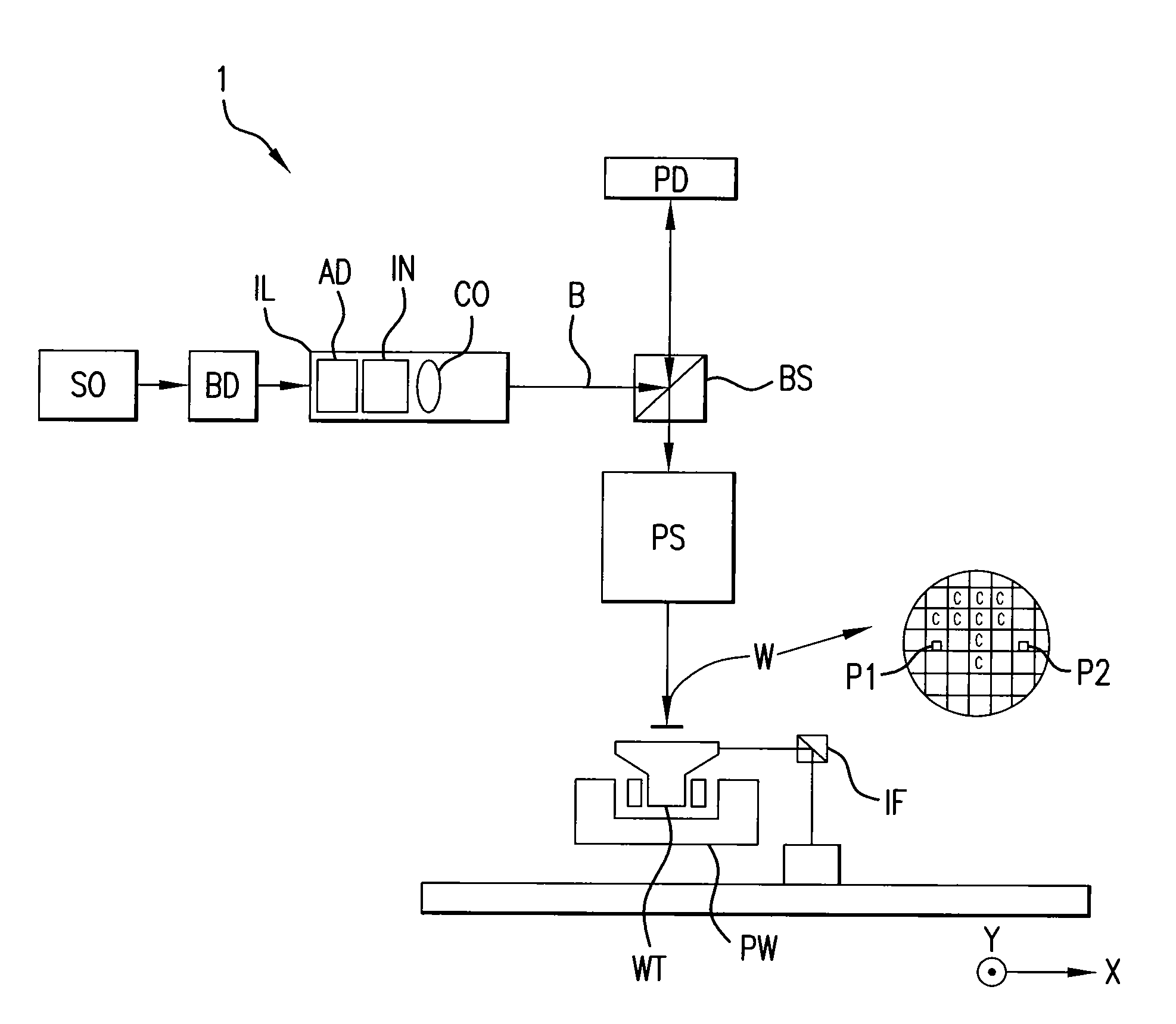
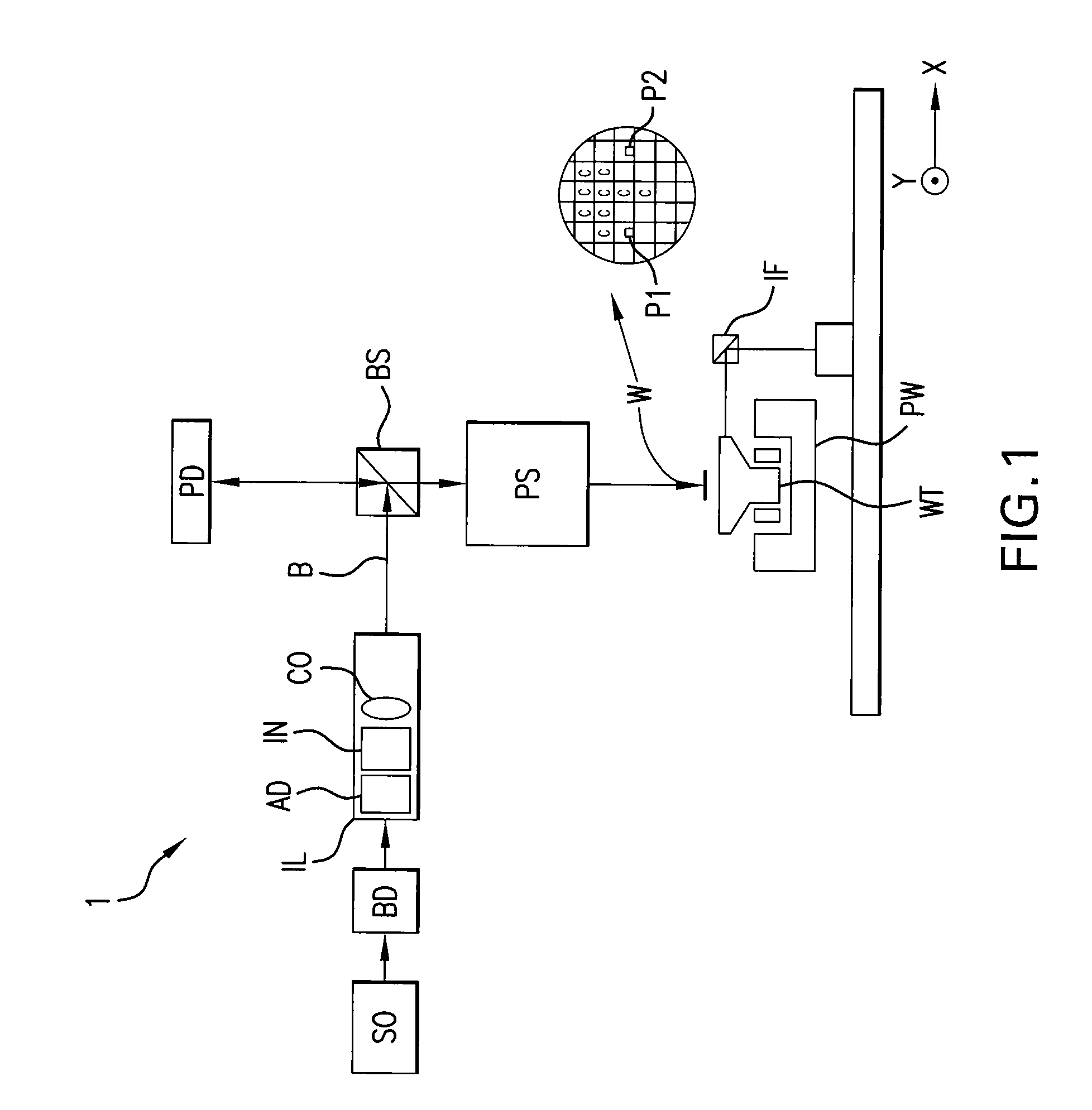
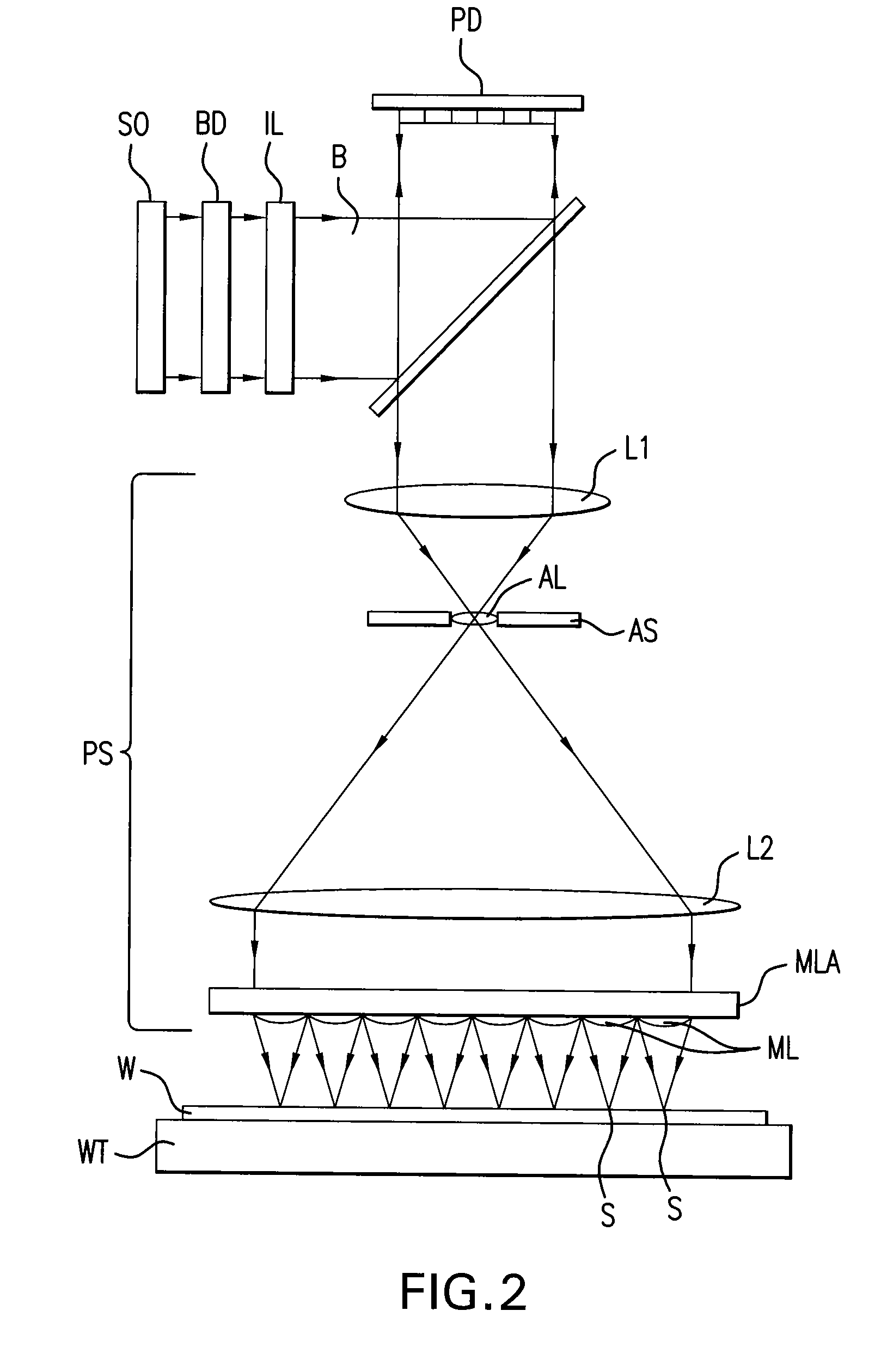
BACKGROUND[0001]1. Field of the Invention[0002]The present invention generally relates to a lithographic apparatus and a method for manufacturing a device. More specifically, the invention relates to a system and method for synchronizing elements of a system for controlling the lithographic apparatus.[0003]2. Related Art[0004]A lithographic apparatus is a machine that applies a desired pattern onto a substrate or part of a substrate. A lithographic apparatus can be used, for example, in the manufacture of flat panel displays, integrated circuits (ICs) and other devices involving fine structures. In a conventional apparatus, a patterning device, which can be referred to as a mask or a reticle, can be used to generate a circuit pattern corresponding to an individual layer of a flat panel display (or other device). This pattern can be transferred onto all or part of the substrate (e.g., a glass plate), by imaging onto a layer of radiation-sensitive material (e.g., resist) provided on t...

Claims


Application Information

Patent Timeline
IPC IPC(8): G03B27/42G06F19/00
CPCG03F7/70491H04L12/403H04J3/0682G03F7/70508
Inventor POULS, ROEL FRANCISCUS
Owner ASML NETHERLANDS BV
Learn More