
Process for the production of hollow bodies of thermoplastic material

a thermoplastic material and hollow body technology, applied in the direction of chemistry apparatus and processes, domestic applications, applications, etc., can solve the problems of difficult production of parts with severely undercut configurations, troublesome integration of manipulators into production cycle, and inability to effectively produce parts by extrusion blow molding process

Active Publication Date: 2009-02-19
KAUTEX TEXTRON
View PDF15 Cites 14 Cited by
  • Summary
  • Abstract
  • Description
  • Claims
  • Application Information

AI Technical Summary

Benefits of technology

[0016]Thus in an advantageous fashion multiple use of the central mold or component holders which are displaceable therein can completely replace a plurality of manipulators which are otherwise required. Such manipulators require a great deal of space for them to be set up, and in addition they are found to be troublesome in regard to the required displacement movement of the tool.

Problems solved by technology

By virtue of the shaping effect by expansion by means of an increased internal pressure or by virtue of applying the preform against the inside wall of the mold by means of vacuum, the extrusion blow molding process is basically not suitable for the production of those parts which are to involve slight wall thickness tolerances.
In addition parts with severely undercut configurations are difficult to produce.
The use of manipulators is rather troublesome in terms of their integration into the production cycle.

Method used


Image

  • Process for the production of hollow bodies of thermoplastic material
  • Process for the production of hollow bodies of thermoplastic material
  • Process for the production of hollow bodies of thermoplastic material

Examples


Embodiment Construction

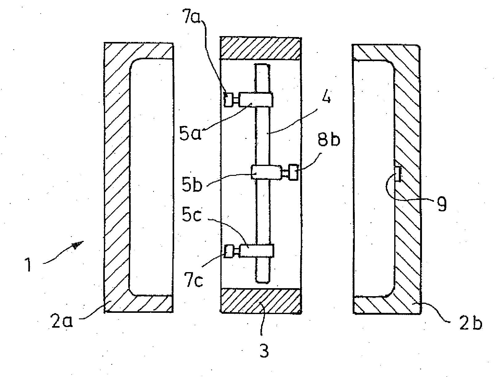
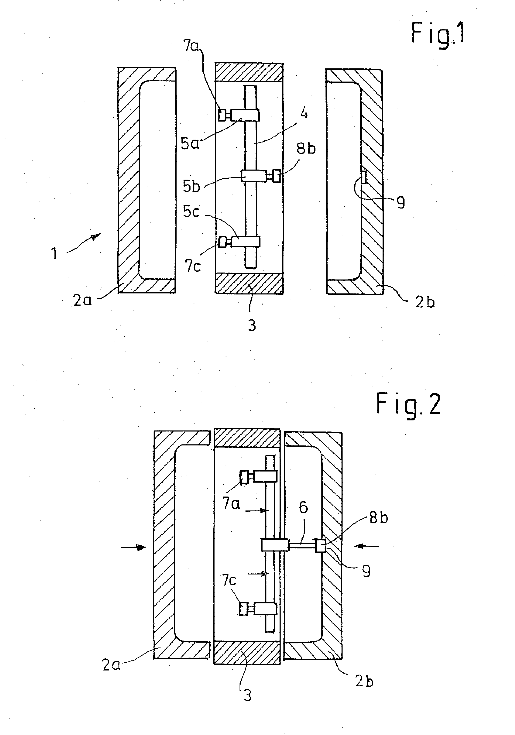
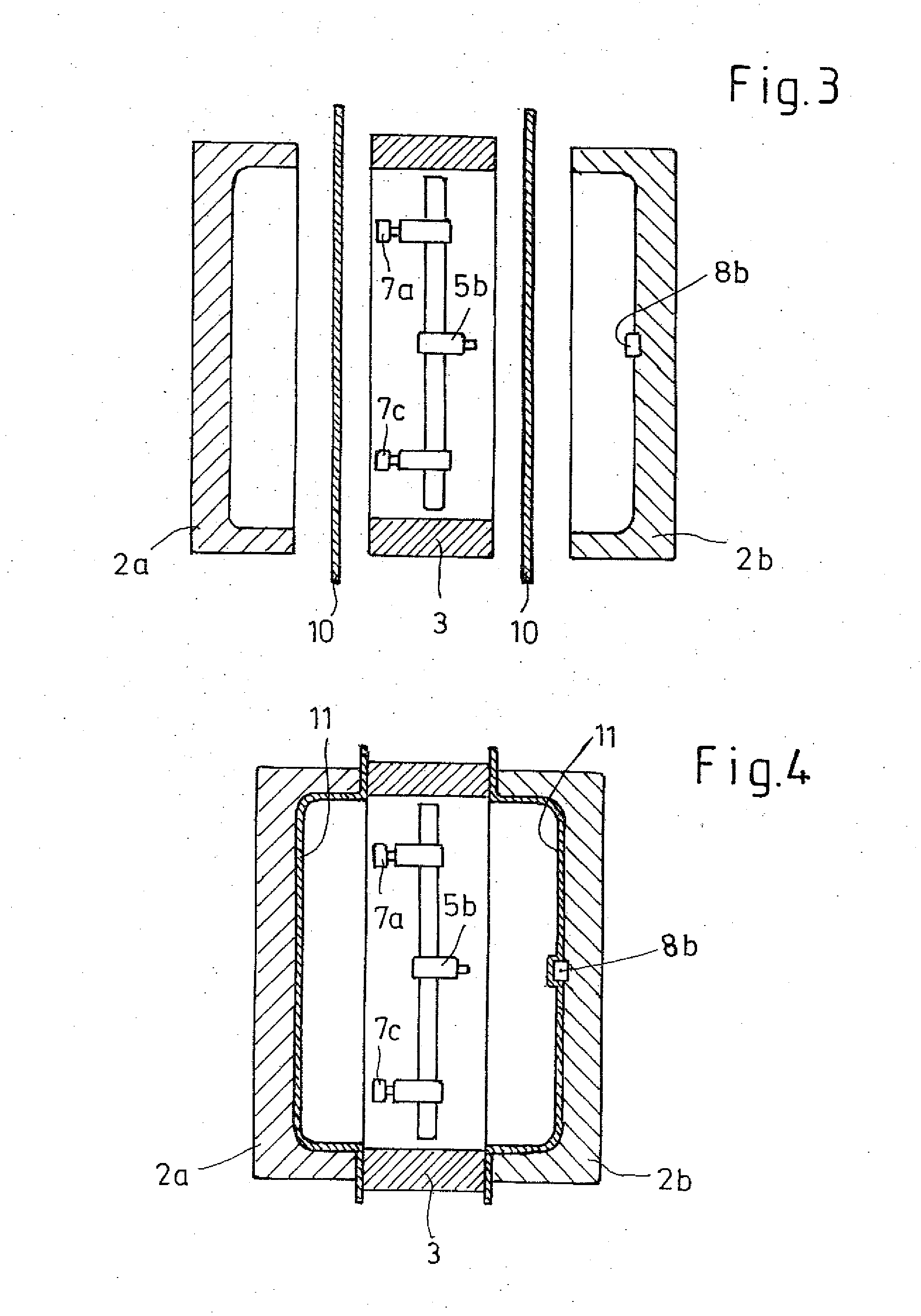
[0019]In the Figures, the tool identified by reference 1 is shown in cross-section, the tool being of a three-part configuration and comprising two outer molds 2a, 2b and a central mold 3. The outer molds 2a, 2b are displaceable away from and towards each other in the sense of an opening and closing movement, while the central mold 3 is displaceable with respect to the outer molds 2a, 2b transversely with respect to the opening and closing movement of the outer molds. The molds are each fixed in known manner to respective known mold mounting plates which are not shown for the sake of simplicity, the mounting plates being displaceable or movable in a closing frame structure which is also not shown. An extrusion device for producing preforms in web or band form is also not shown for reasons of simplification. By way of example, with reference to FIG. 1, two suitable extrusion heads with wide-slot nozzles can be arranged above the tool 1 on the side towards the person viewing the drawi...


PUM

PropertyMeasurementUnit
pressureaaaaaaaaaa
heataaaaaaaaaa
thicknessaaaaaaaaaa

Abstract

The invention concerns a process for the production of hollow bodies of thermoplastic material. In the process according to the invention preforms in web or band form of plasticized material are shaped in a multi-part tool forming a mold cavity comprising two outer molds and at least one central mold which perform an opening and closing movement relative to each other. The central mold is provided with at least one component holder which can be moved of and into the tool plane defined by the central mold. In a first step the component holder is fitted with at least one insert portion, then the insert portion is placed by means of the component holder against the inside wall of an outer mold. In a further step introduction and shaping of the preforms within the tool is effected in a two-stage procedure, wherein firstly the preforms are respectively applied against a contour forming a part of the mold cavity by means of increased pressure and / or reduced pressure and shaped and then the intermediate products forming respective parts of the hollow body are joined together to form a finished product.

Description

CROSS-REFERENCE TO RELATED APPLICATIONS[0001]This application claims priority to German Application DE 10 2006 027 256, filed Jun. 9, 2006 and to U.S. Provisional Application 60 / 806,491 filed Jul. 3, 2006.FIELD[0002]The invention concerns a process for the production of hollow bodies of thermoplastic material by extrusion blow molding.BACKGROUND[0003]The operation of extrusion blow molding plastic products usually involves using mold tools which comprise two mold halves which are of a mutually complementary configuration and which jointly define a mold cavity. A thermoplastic extrudate, generally in the form of a tube, is placed between the opened halves of the tool. The tool closes around the preform and the preform is applied within the tool against the inside wall of the cavity formed by the tool so that the finished article is of an external configuration corresponding to the internal contour of the mold tool. Shaping of the preform within the cavity of the tool is effected eith...

Claims


Application Information

Patent Timeline
Patent Type & Authority Applications(United States)
IPC IPC(8): B32B1/08
CPCB29C49/0047B29C49/04B29C49/20B29C51/12B29C51/267B29L2031/7172B29C2049/2017B29C2049/2073B29C2791/006B29C2791/007B29C2049/0057B29C49/06914B29C49/0691B29C49/5606
Inventor BORCHERT, MATTHIASEULITZ, DIRKWOLTER, GERDKRAMER, TIMOLORENZ, HARALDBIENHULS, DENIZMEHREN, CHRISTOPHLOWER, ROBERT
Owner KAUTEX TEXTRON
Learn More