
Camshaft phaser wiper seal with integral spring

Inactive Publication Date: 2009-02-19
DELPHI TECH INC
View PDF3 Cites 17 Cited by
  • Summary
  • Abstract
  • Description
  • Claims
  • Application Information

AI Technical Summary

Benefits of technology

[0010]Briefly described, a wiper seal for preventing leakage of oil between advance and retard chambers formed between rotor vanes and stator lobes in a vane-type camshaft phaser in accordance with the invention combines a spring element and a wiper element in a monolithic structure and is manufactured from a single composite material by injection molding. The wiper seal is provided at the tip of each rotor vane and / or stator lobe of a vane-type camshaft phaser for varying the timing of combustion valves in an internal combustion engine. The vane-type camshaft phaser includes a rotor having a plurality of vanes disposed in a stator having a plurality of lobes, the interspersion of vanes and lobes defining a plurality of alternating valve timing advance and valve timing retard chambers with respect to the engine crankshaft. During rotation of the rotor within the stator, the tips of the vanes sweep past concave cylindrical walls of the stator, and the tips of the lobes sweep past convex cylindrical walls of the rotor hub. In the case where wipers are provided at both the stator wall and rotor hub positions, each vane and lobe tip is provided with an axially extending groove. The wiper seal in accordance with the invention is disposed in the groove for wiping the opposing wall, such as the stator wall and / or rotor hub. The wiper seal in accordance with the invention is designed as a potential drop-in replacement for existing prior art wiper seals, thereby eliminating the need for changing the design of the vane and lobe tips.
[0011]The wiper seal in accordance with the invention includes a spring element that is designed as a cantilevered arm and provides sealing pressure to the wiper element. The cantilevered arm is positioned on the back of the wiper element and comes in contact with the wiper element at a secondary contact point during installation forming an arch. The secondary contact point increases a sealing force across the face of the wiper compared to prior art wiper seals thereby providing improved reliability. The secondary contact point also distributes the sealing force across the face of the wiper evenly and prevents over-travel and over-stress of the cantilevered arm.
[0012]The wiper seal in accordance with the invention further includes a rib element that extends the back of the wiper element and that is positioned under the cantilevered arm. The rib element assists in preventing over-compression of the cantilevered arm and in preventing tangling of a plurality of wiper seals during handling and shipping.
[0013]By designing the wiper seal in accordance with the present invention as a monolithic structure manufactured from a single composite material during a single manufacturing step, the manufacturing costs and process cycle time can be reduced compared to prior art wiper seals based on elimination of plasma treatment and elastomer insert molding steps. Lower cost materials can be used in the wiper seal in accordance to the present invention compared to prior art, wiper seals due to elimination of the exposure of the material to plasma treatment and elastomer insert molding pressures and temperatures. Furthermore, it is believed that the composite material used in accordance with the present invention exhibits better wear characteristics against aluminum than material used for known prior art wiper elements.

Problems solved by technology

This configuration requires two separate manufacturing steps, one successive assembly step, and two different materials to provide a one-piece wiper seal subassembly, creating undesired manufacturing and subassembly costs as well as complexity.

Method used


Image

  • Camshaft phaser wiper seal with integral spring
  • Camshaft phaser wiper seal with integral spring
  • Camshaft phaser wiper seal with integral spring

Examples


Embodiment Construction

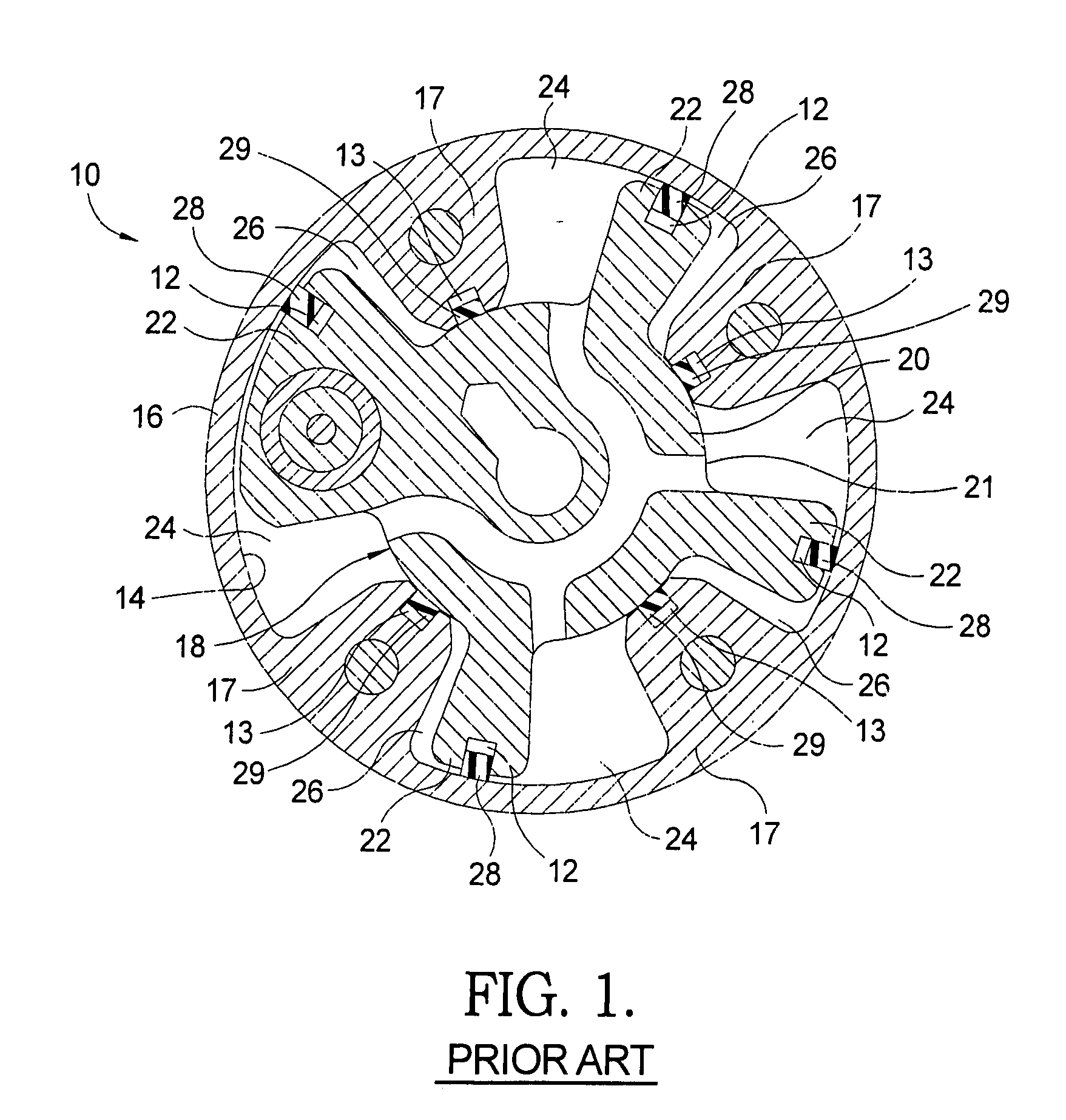
[0025]Referring to FIG. 1, an exemplary prior art vane-type camshaft phaser 10 for advancing and retarding the timing of valves of an internal combustion engine includes well-known generic components: a stator 16 having a plurality of inwardly extending lobes 17; a rotor 18 having a cylindrical hub 20 and a plurality of outwardly extending vanes 22; and a plurality of advance chambers 24 and retard chambers 26 being formed between the rotor vanes 22 and the stator 16. The lobes 17 are circumferentially spaced apart for receiving rotor 18. Vanes 22 extend into spaces between lobes 17. Hydraulic advance chambers 24 and retard chambers 26 are thus formed between lobes 17 and vanes 22. Each rotor vane 22 is provided with an axial groove 12 along the vane tip for receiving a resilient seal element 28 for sealingly wiping a cylindrically concave inner wall 14 of stator 16. Likewise, each stator lobe 17 is provided with an axial groove 13 along the lobe tip for receiving a resilient seal e...


PUM


Abstract

A wiper seal for preventing leakage of oil between advance and retard chambers formed between rotor vanes and stator lobes in a vane-type camshaft phaser is a monolithic structure made from a single material that includes a wiper element and a compressible spring element extending from the wiper element. The spring element is designed as a cantilevered arm and provides a sealing pressure to the wiper element. The wiper seal may further include a rib element as part of the monolithic structure that vertically extends the wiper element towards the spring element. The rib element assists in preventing over-compression of the cantilevered arm and in preventing tangling of a plurality of wiper seals during handling and shipping. The wiper seal is provided at the tip of each rotor vane and / or stator lobe of a vane-type camshaft phaser for varying the timing of combustion valves in an internal combustion engine.

Description

TECHNICAL FIELD[0001]The present invention relates to hydraulic valve timing devices of internal combustion engines; more particularly, to vane-type camshaft phasers; and most particularly, to an improved compressible wiper seal for disposal in rotor vanes and / or stator lobes of a camshaft phaser.BACKGROUND OF THE INVENTION[0002]Camshaft phasers for varying the phase relationship between the crankshaft and a camshaft of an internal combustion engine are well known. A prior art vane-type phaser generally comprises a plurality of outwardly extending vanes on a rotor interspersed with a plurality of inwardly extending lobes on a stator, forming alternating advance and retard chambers between the vanes and lobes. Engine oil is supplied via a multiport oil control valve (OCV), in accordance with an engine control module, to either the advance or retard chambers as required to meet current or anticipated engine operating conditions.[0003]In a typical prior art vane-type camshaft phaser, a...

Claims


Application Information

Patent Timeline
IPC IPC(8): F01L1/344F01D11/00F04D29/00F16J15/16F01L1/34
CPCF01L1/3442Y10T74/2102F01L2001/34479
Inventor SCOTT, MATTHEW T.MCCARTHY, DAVID M.LICHTI, THOMAS H.WEISS, AMANDA M.
Owner DELPHI TECH INC
Learn More