
Digital comb limiter combiner

a limiter combiner and digital comb technology, applied in the direction of transmission, electrical equipment, etc., can solve the problems of reducing the physical range from which the signal intelligence receiver can receive signals, reducing the physical range of the signal intelligence receiver, so as to protect amplifiers and limiters in the receiver front end from strong interference outside the communications signal bandwidth

Active Publication Date: 2009-02-12
VECTRUS SYST CORP
View PDF1 Cites 17 Cited by
  • Summary
  • Abstract
  • Description
  • Claims
  • Application Information

AI Technical Summary

Benefits of technology

"The patent text describes a problem in signal intelligence receivers where strong intermodulation products from multiple transmitters can reduce the range of the receiver. The problem is caused by noise sources that act as mixers, and there is no simple way to filter out these intermodulation products. The patent proposes a solution using a digital comb limiter combiner, which filters out intermodulation products and allows for effective detection of low-power signals in the presence of strong interferers. The patent also describes various methods for adjusting the excision threshold, pass bands, and gain of the components in the receiver to optimize performance."

Problems solved by technology

This ability to intercept radio signals may be compromised by noise sources that effectively reduce the physical range from which the signal intelligence receiver can pick signals of interest from their origins.
Frequency-hopping, frequency-scanning wideband and ultra-wideband communications receivers cannot employ simple passive narrowband preselector filters to protect amplifiers and limiters in receiver front ends from strong interference outside the communications signal bandwidth.
Close proximity to multiple transmitters reduces the effective communications range of such receivers to almost zero.
This has shown some improvement, yet this approach leaves much of the interfering signal energy present for the radio receiver to attempt to differentiate from the desired signal.

Method used


Image

  • Digital comb limiter combiner
  • Digital comb limiter combiner
  • Digital comb limiter combiner

Examples


Embodiment Construction

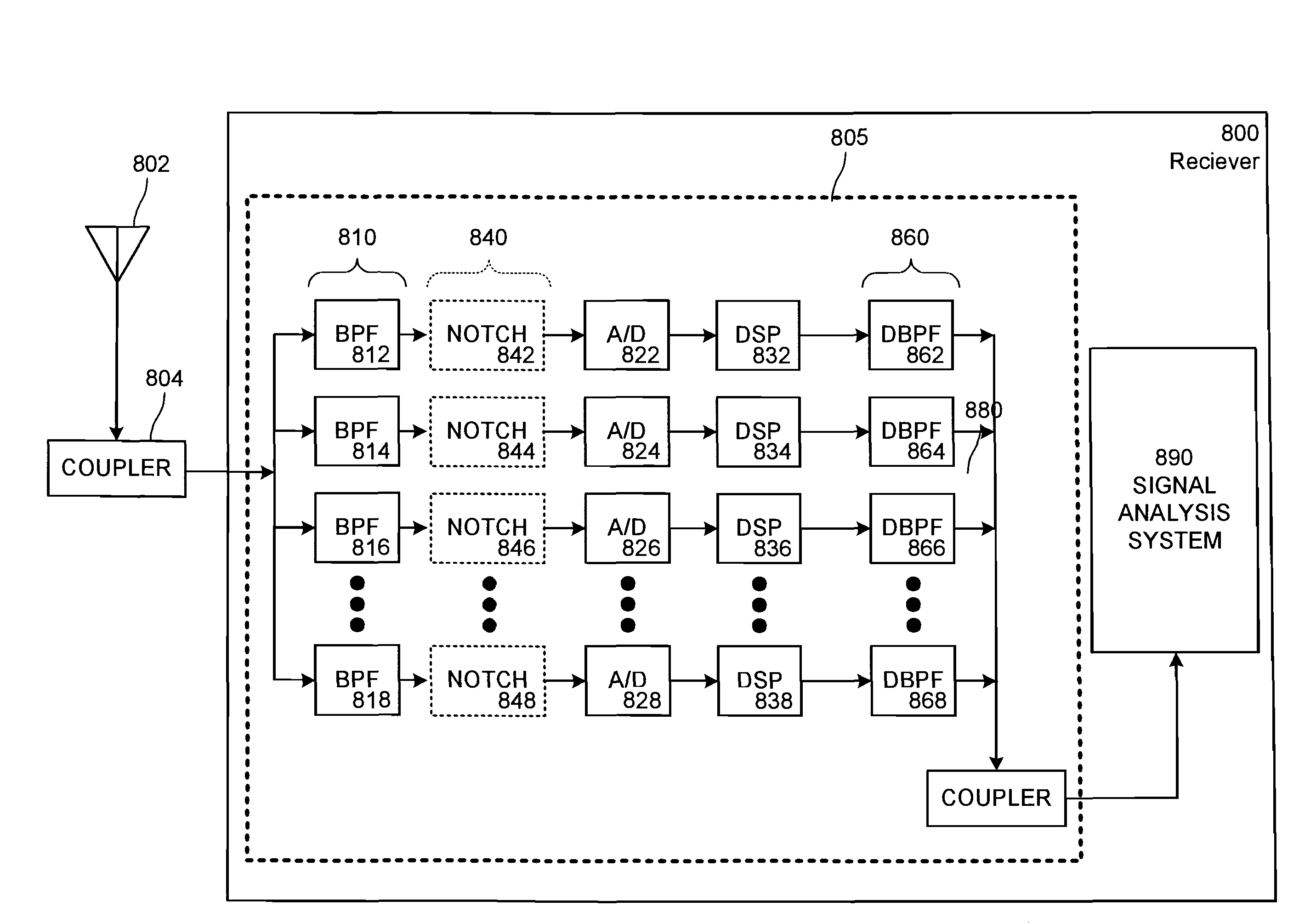
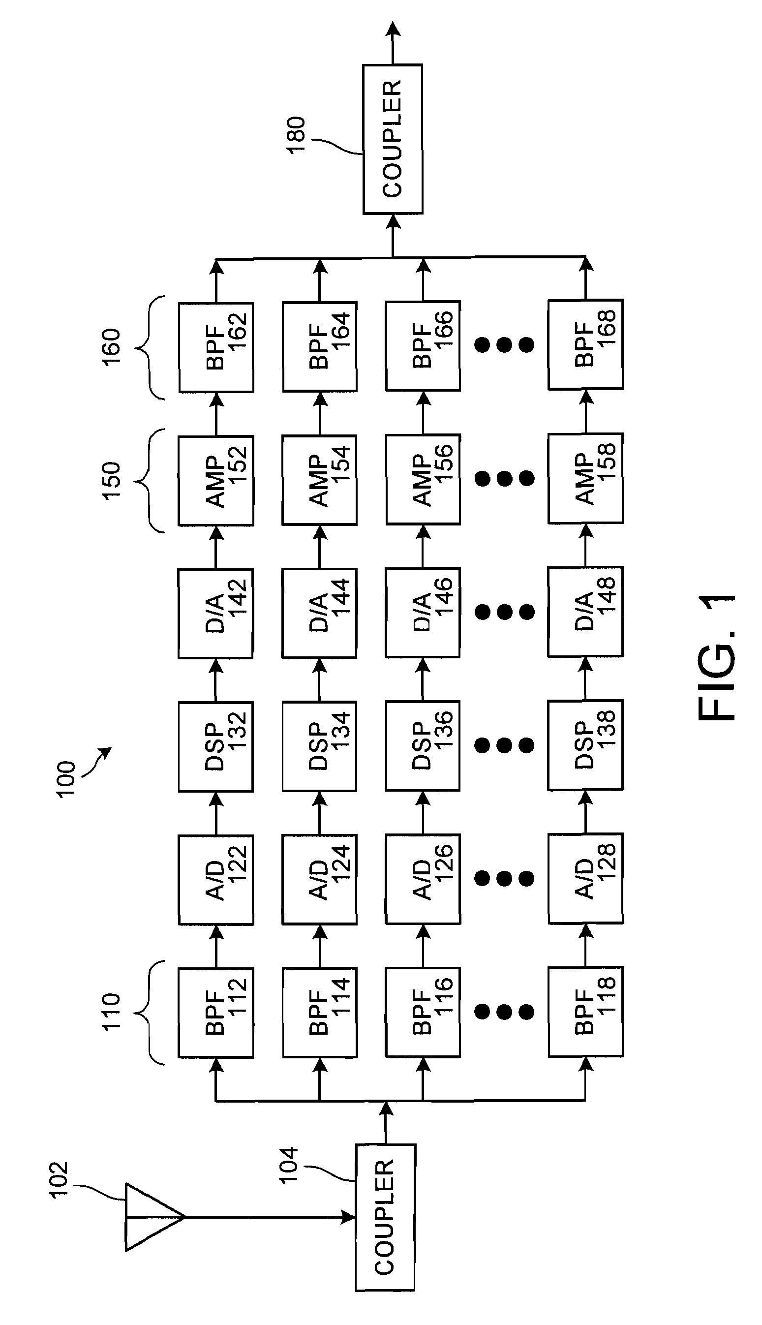
[0024]The comb filter banks at the input and output of the receiver divide the waveforms into different frequency sub-bands. Each comb limiter combiner (CLIC) sub-band is substantially narrower than 50 MHz, for example about 5 MHz wide. Within each sub-band, the high-power interference is processed to reduce levels to the spurious-free dynamic range of signal intelligence and electronic intelligence (SIGINT / ELINT) receivers. The CLIC accomplishes this without generating significant intermodulation products.

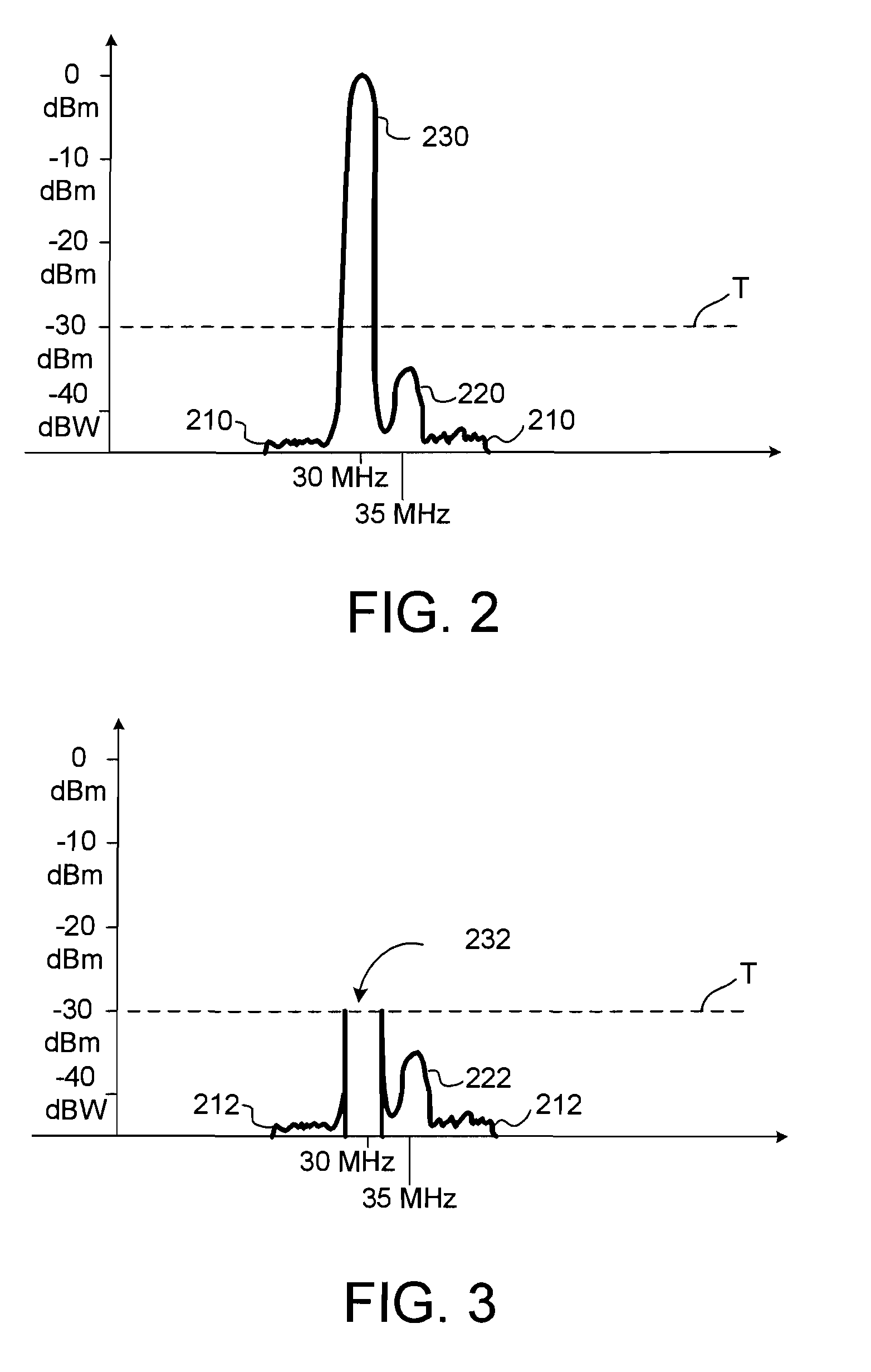
[0025]By digitizing the signal within each of the sub-bands, digital signal processing technology can be brought to bear on the signal. In particular, strong interfering signals in close proximity in the frequency spectrum to a signal of interest can be dealt with using frequency excision. By this technique the bulk of the energy of the strong interfering signal is removed while leaving undisturbed a substantial amount of the energy of the signal of interest.

[0026]The embodiments ...


PUM


Abstract

A wideband receiver comprises a comb limiter combiner wherein the limiting is conducted by digitization and frequency excision in the frequency domain. The received signal is divided up into sub-bands by a bank of bandpass filters having contiguous pass bands spanning the entire receiver range. In each sub-band the band limited signal is digitized and subjected to digital signal processing. A threshold is set such that any frequency with a magnitude that exceeds the threshold is excised in the frequency domain. When converted back to the time domain, the high-power interference frequencies will no longer be present, thereby leaving only the low-power noise and the desired signal.

Description

CROSS REFERENCE TO RELATED APPLICATIONS[0001]This application claims the benefit of Provisional Application No. 60 / 916,868 filed May 9, 2007, Provisional Application No. 60 / 916,867 filed May 9, 2007, Provisional Application No. 60 / 917,205 filed May 10, 2007 and Provisional Application No. 60 / 917,203 filed May 10, 2007′. The 60 / 916,868, 60 / 916,867, 60 / 917,205 and the 60 / 917,203 applications are incorporated by reference herein, in their entireties, for all purposes.BACKGROUND AND SUMMARY[0002]A signal intelligence receiver intercepts radio signals at a high sensitivity across a large bandwidth of the radio spectrum. This ability to intercept radio signals may be compromised by noise sources that effectively reduce the physical range from which the signal intelligence receiver can pick signals of interest from their origins. Frequency-hopping, frequency-scanning wideband and ultra-wideband communications receivers cannot employ simple passive narrowband preselector filters to protect ...

Claims


Application Information

Patent Timeline
Patent Type & Authority Applications(United States)
IPC IPC(8): H04B1/18
CPCH04B1/1036
Inventor MAIUZZO, MICHAEL A.
Owner VECTRUS SYST CORP
Learn More