
Tunnel cover for a tunnel for controlled ventilation of gas

Inactive Publication Date: 2009-02-12
KUMM MARIA +1
View PDF6 Cites 13 Cited by
  • Summary
  • Abstract
  • Description
  • Claims
  • Application Information

AI Technical Summary

Benefits of technology

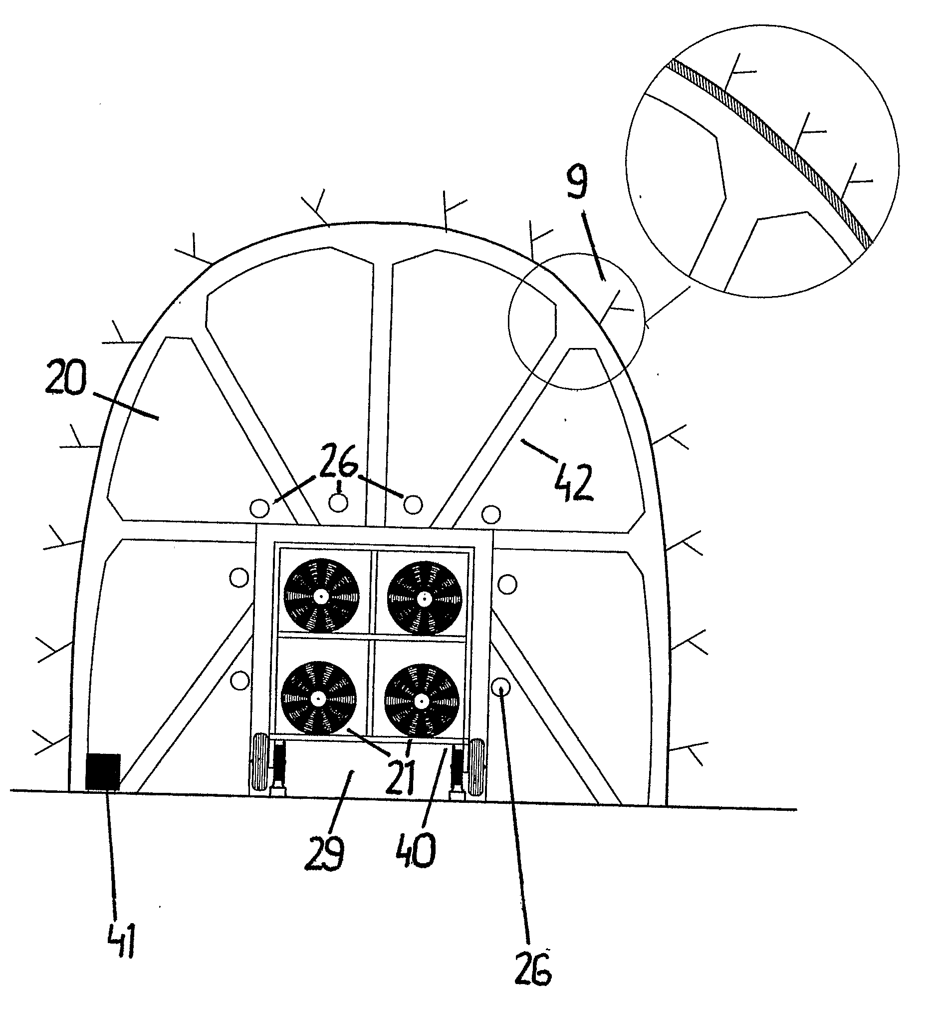
[0042]One advantage of the invention at hand is that it makes effective ventilation of a tunnel possible in the event of fire without the need of having fixed and powerfully dimensioned fans permanently installed in the tunnel.
[0043]One of the most important advantages of the invention is that the capacity of the fan that is required in order to ventilate a tunnel can be lowered considerably by using the cover at the mouth of the tunnel. Instead of needing to procure special fans in order to be able to ventilate the types of environment described, in the event of fire, it will now be possible to use the fans that are available at local emergency services. Numerous emergency service vehicles are already equipped with mobile fans, used to ventilate buildings such as private homes, commercial premises and apartment buildings. One significance of the invention is that emergency services will have the possibility of utilising ventilation as a working method during outbreaks of fire or emissions in tunnels, a method, which has not at all been the case using previous known techniques. It also leads to increased cost effectiveness since newer and larger fans need not be procured, an increased total efficiency as existing equipment can be used in more environments, and that the costs to society will be lower since the local emergency services will increase their capacity to extinguish fires in tunnels.
[0044]A further advantage of the invention in question is that it enables rescue operations to be considerably safer than when using previous known techniques, as the invention makes it possible to ventilate smoke, fire fumes away or combustion as, prior to commencement of rescue work, to a greater extent than when using earlier known techniques.
[0045]A membrane is foldable, and in one embodiment inflatable, which enable either storage of the membrane at the mouth of the tunnel. The membrane may also be intended to be transported in a compact and space saving manner, for instance on a rescue vehicle.
[0046]Yet another object of the invention is to provide a method to generate a sufficient flow through a tunnel in order to ventilate the tunnel of smoke, combustion gas and other gases / aerosols. The method comprises the step of establishing a flow of air by means of at least one mobile fan through the opening in the membrane.

Problems solved by technology

Experience from major fire accidents in tunnels show that rescue operations at sites of fire or other events / accidents in tunnels raise problems for emergency services.
One of the problems arises from the fact that the great majority of tunnels usually are underground, limiting the number of exits / entrances.
Another problem is that, usually, smoke cannot be ventilated away vertically from a fire in a tunnel; the tunnel becomes filled with smoke.
Most modern road tunnels currently in use are ventilated by means of a fixed installation of a longitudinal ventilation system in the tunnel chamber, which can be used in the event of fire, whilst most types of railway tunnels and technical supply tunnels lack any possibility of removing smoke from a fire by means of ventilation.
This means that, in many cases, the emergency services have great difficulty in carrying out fire and rescue operations.
This aspect of safety concepts seems, by and large, to be very poorly analysed and very few pertinent analyses are officially available, in disparity with most other aspects of the safety concept for tunnel environments.
As a consequence there is no possibility to control the spread of smoke and large parts of such tunnels fill with smoke during a fire.
This seriously weakens the possibilities of carrying out effective rescue operations and saving lives.
Without feasibility for fire ventilation the spread of smoke from a fire in a single tubular tunnel can entail advanced smoke-helmeted operations before fire-fighting can commence.
Such actions may need to take place in a smoke-filled area, which means that the personnel involved need protective clothing and equipment.
Such actions may also need to be carried out in a dangerous environment with smoke and high levels of heat radiation, which means that the personnel taking part may need protective clothing and equipment.
These actions, too, may need to take place in a dangerous environment with smoke and high-level heat radiation, which means that the personnel may need to have protective clothing and equipment.Actions in a tunnel to rescue or assist people and facilitate survival in the tunnel.
These actions may also need to take place in a dangerous environment with smoke and high-level heat radiation, which means that the personnel may need to have protective clothing and equipment.Ventilation of a tunnel to control the flow and direction of smoke in the tunnel.
This method will probably requires large resources if the number of people injured is high.
Rescue operations in tunnels require a major part of the taskforce working in a smoke-filled environment, if the ventilation available cannot ensure a smoke-free environment for the work involved.
It is a highly limiting factor towards efficient results.
The range of a smoke-diving operation is limited partly by regulations for industrial welfare, which govern the form of an operation, and partly by the possibility of getting close to the site of the fire because of the environment in the tunnel and access to breathable air.
When it comes to fires in tunnels the method has not succeeded in achieving an effective airflow and thereby not the effect intended.
The result has been far from good as it has not been possible to create a sufficiently strong airflow in tunnels.
This entails a hazardous working environment for rescue workers and an inferior result of the emergency operation.
One problem that remains in respect of ventilation of a tunnel during a fire, or other similar occurrence, is to create a sufficiently large longitudinal airflow along the length of a relatively long tunnel with no fixed fans.

Method used


Image

  • Tunnel cover for a tunnel for controlled ventilation of gas
  • Tunnel cover for a tunnel for controlled ventilation of gas
  • Tunnel cover for a tunnel for controlled ventilation of gas

Examples


Embodiment Construction

[0053]As mentioned earlier, experience and various forms of tests show that the maximum range of smoke-diving operations in smoke-filled but not particularly hot environments lies between 100-150 metres. Many tunnels are considerably longer than 100-150 metres. The inventors have come to the conclusion that it is an essential advantage to carry out ventilation to increase accessibility when fires occur in longer tunnels. In such cases of fire, ventilation is an effective method towards enabling rescue operations to be carried out.

[0054]Ventilation of smoke and / or combustion gases, in accordance with the invention, facilitates both rescue operations and evacuation of people affected by fire or emission of dangerous substances in a tunnel. During a situation involving fire, the function of the fan is to create an airflow in the tunnel of sufficient velocity that it takes away the smoke or other gases / aerosols from a designated area in the tunnel. This is in order to create the possibi...


PUM


Abstract

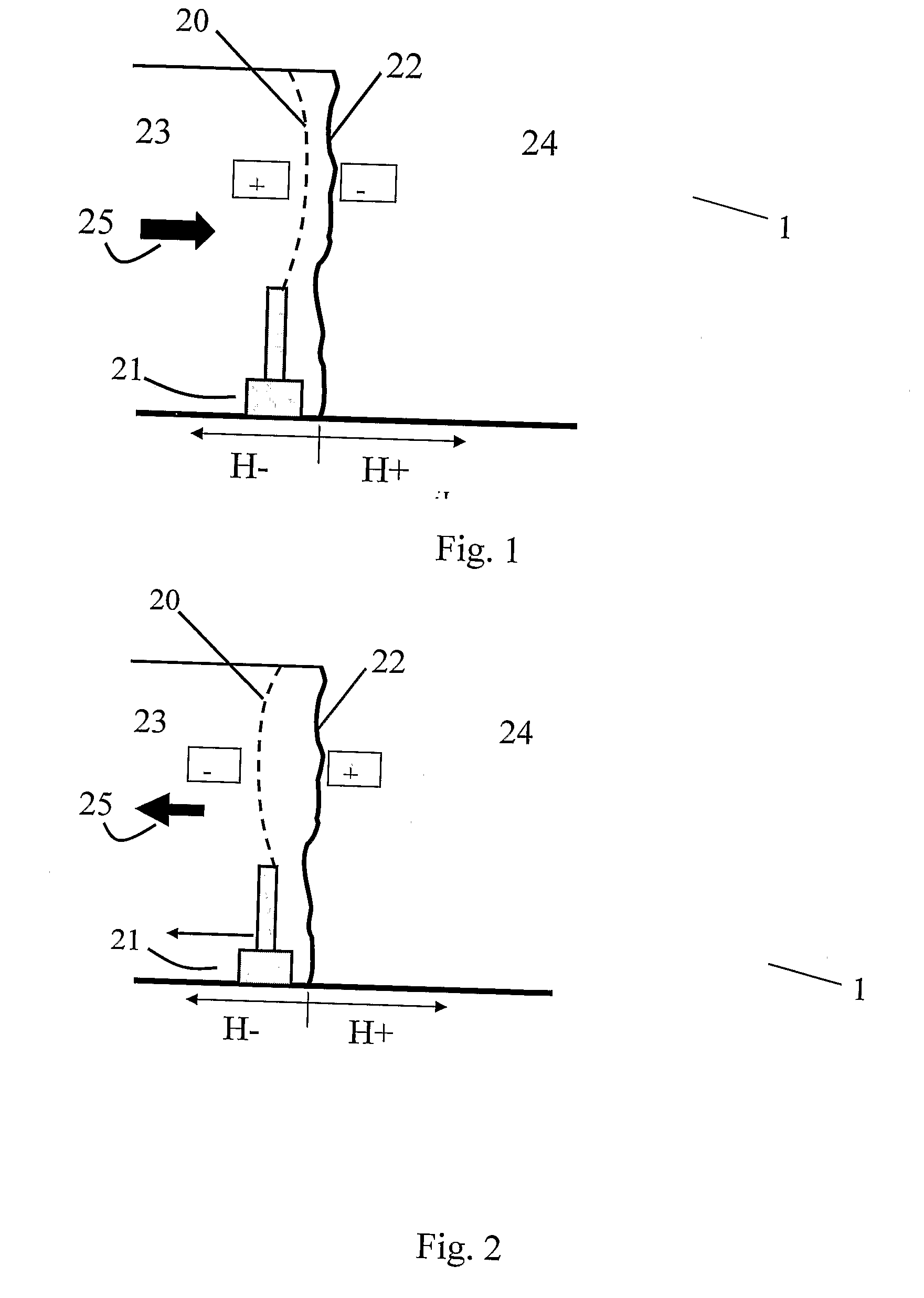
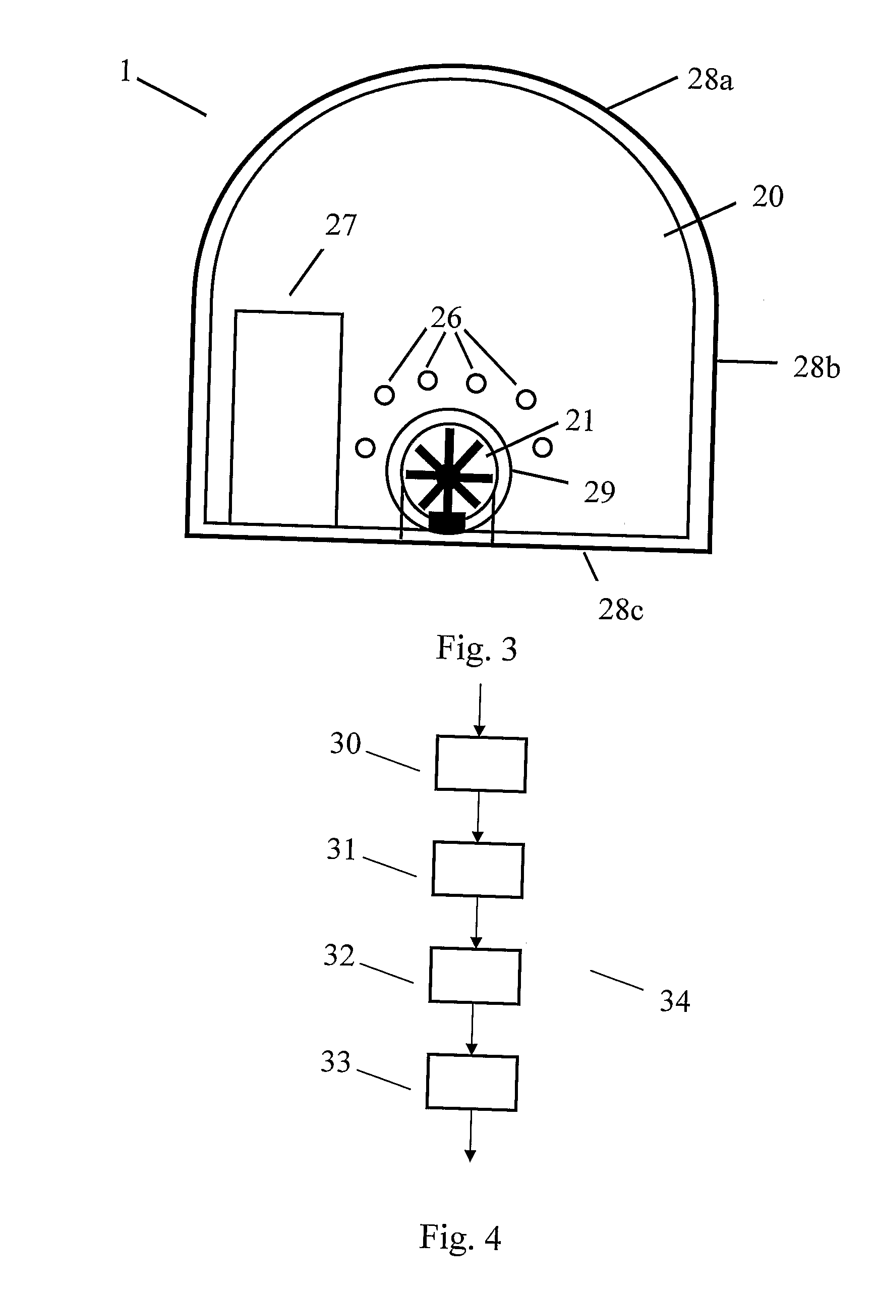
A system, in accordance with the invention, relates to ventilating a tunnel 1 in the event of fire or emission of gases C or aerosols. The system comprises a tunnel cover 20 and a mobile fan 21. The tunnel cover 20 has an opening 29 through which the fan 21 blows air. This increases the static pressure at the cover 20, which change the direction of air at a desired direction. One of the advantages of the invention is that the tunnel cover 20 makes it possible to utilise considerably smaller mobile fans 21 to ventilate a tunnel 1 in the event of fire or emission of gases than when using earlier known techniques.

Description

TECHNICAL FIELD[0001]The invention concerns devices, methods and systems for ventilation of tunnels in the event of fire, emission of dangerous or unhealthy chemicals and other similar events.BACKGROUND ART[0002]Experience from major fire accidents in tunnels show that rescue operations at sites of fire or other events / accidents in tunnels raise problems for emergency services. Examples of alternative terms used for emergency services are: fire department, fire protection service, fire brigade or civil defence. In the text that follows, “fires and smoke” is used to describe the technical standpoint. Equivalents could be described by using dangerous or unhealthy gases or aerosols, which, for some reason have been emitted in a tunnel. One of the problems arises from the fact that the great majority of tunnels usually are underground, limiting the number of exits / entrances. Another problem is that, usually, smoke cannot be ventilated away vertically from a fire in a tunnel; the tunnel ...

Claims


Application Information

Patent Timeline
IPC IPC(8): E21F1/00A62C3/00E21FE21F1/08E21F1/14E21F1/16E21F5/00
CPCE21F1/145E21F1/08E21F5/00
Inventor KUMM, MARIABERGQVIST, ANDERS
Owner KUMM MARIA
Learn More