Image forming apparatus and method of performing density correction
a technology of density correction and image forming apparatus, which is applied in the direction of electrographic process apparatus, instruments, optics, etc., can solve the problem of image quality deterioration upon printing
- Summary
- Abstract
- Description
- Claims
- Application Information
AI Technical Summary
Benefits of technology
Problems solved by technology
Method used
Image
Examples
first embodiment
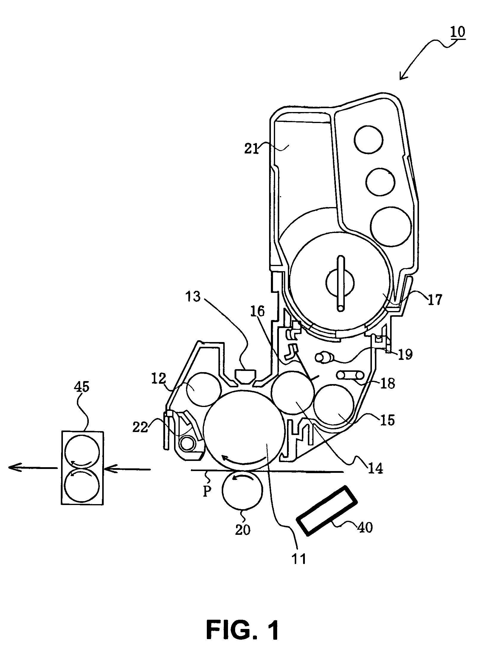
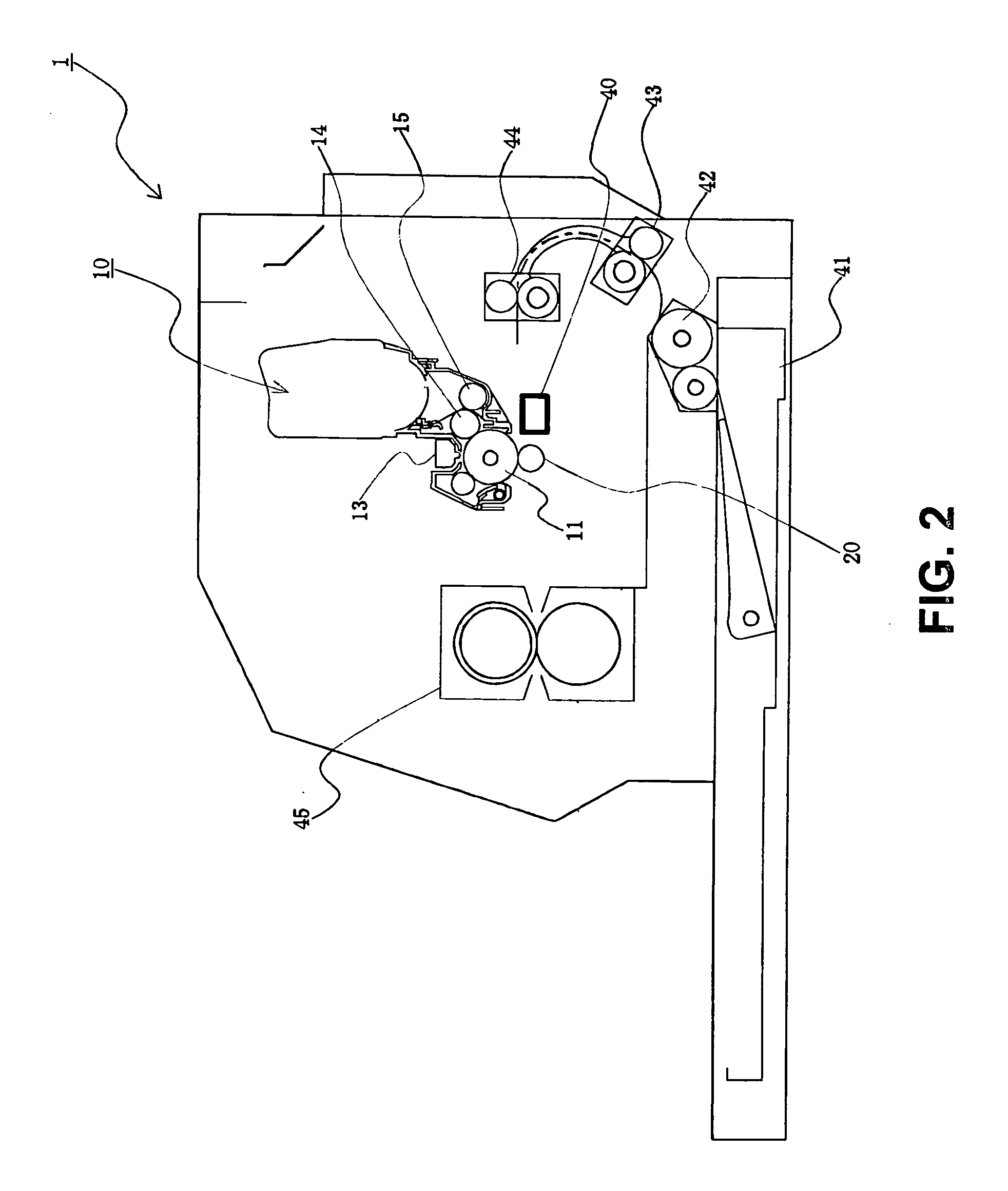
[0031]A first embodiment of the present invention will be explained. FIG. 1 is a schematic sectional view showing an image forming unit 10 according to the first embodiment of the present invention. FIG. 2 is a schematic sectional view showing an image forming apparatus 1 according to the first embodiment of the present invention.
[0032]In the embodiment, the image forming apparatus 1 may be a printer, a copier, a facsimile, a multifunction product, and the likes. In the following description, the image forming apparatus 1 is a printer of an electro-photography type for forming an image with an electro-photography method. Further, the image forming apparatus 1 is the printer for forming a monochrome image, and may be a printer for forming a color image.
[0033]In the embodiment, the image forming apparatus 1 is provided with a tray 41 for storing a recording medium P as a medium, the image forming unit 10, and a fixing device 45. As shown in FIG. 2, a hopping roller 42 is provided for ...
second embodiment
[0122]A second embodiment of the present invention will be described below. In the description below, elements in the second embodiment similar to those in the first embodiment are designated by same reference numerals, and explanations thereof are omitted. Explanations of operations and effects in the second embodiment similar to those in the first embodiment are omitted.
[0123]FIG. 12 is a schematic sectional view showing the image forming apparatus 1 according to the second embodiment of the present invention.
[0124]As shown in FIG. 12, the image forming apparatus 1 is provided with four image forming units 10 arranged in a transportation direction of the recording medium P for forming toner images using the toner 17 in yellow, magenta, cyan, and black, respectively. The image forming units 10 are arranged in tandem, thereby forming a color image.
[0125]In the embodiment, a transfer belt 46 and the transfer rollers 20 are disposed under the photosensitive drum 11 as an intermediate ...
third embodiment
[0155]A third embodiment of the present invention will be described below. In the description below, elements in the third embodiment similar to those in the first and second embodiments are designated by same reference numerals, and explanations thereof are omitted. Explanations of operations and effects in the third embodiment similar to those in the first and second embodiments are omitted.
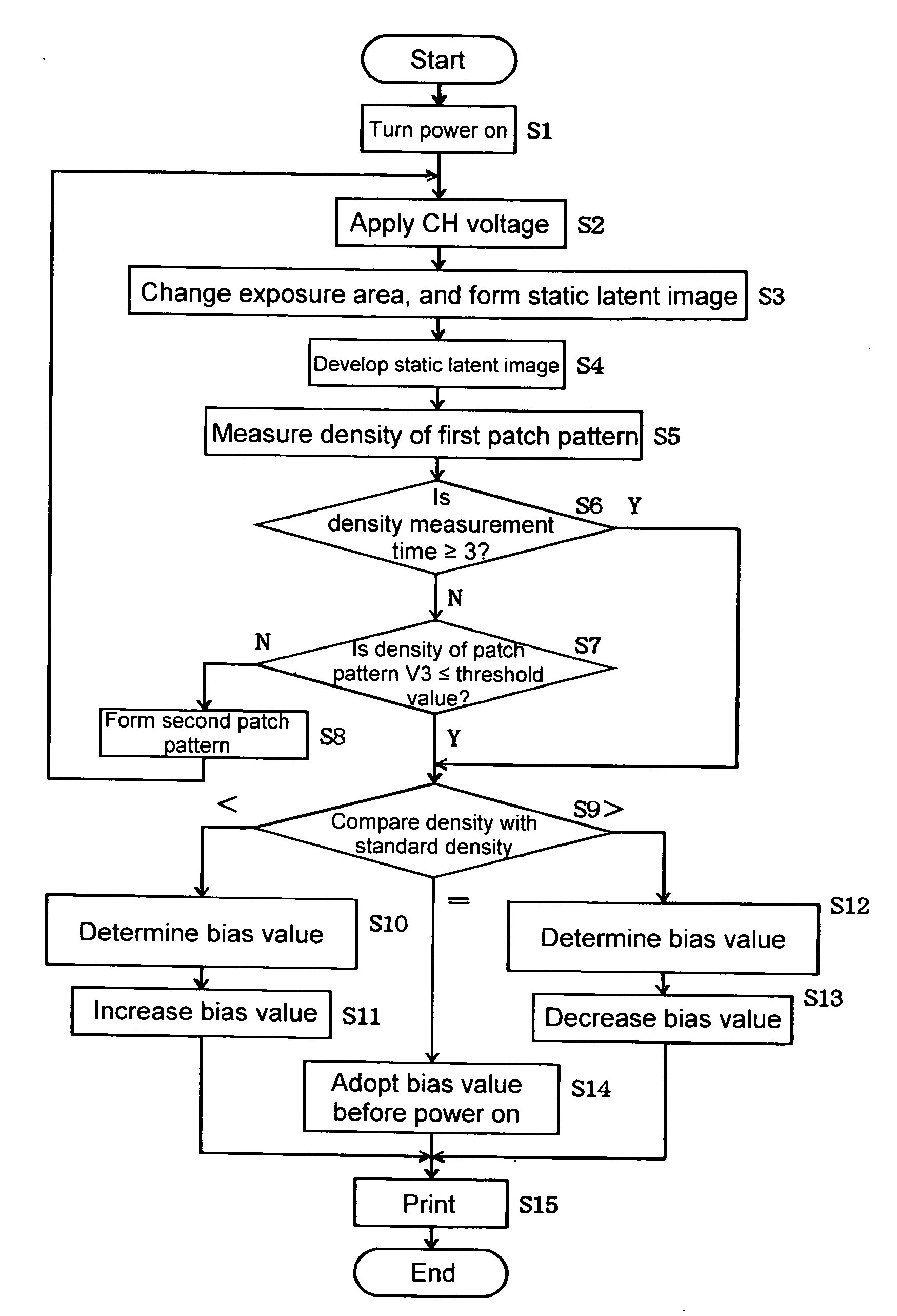
[0156]FIG. 19 is a flow chart showing an operation of the image forming apparatus 1 according to a third embodiment of the present invention. FIG. 20 is a schematic view showing a patch pattern according to the third embodiment of the present invention.
[0157]In the third embodiment, the image forming apparatus 1 has a configuration similar to that in the second embodiment, and an explanation thereof is omitted. An operation of the density correction will be explained.
[0158]When the image forming apparatus 1 is turned on, a voltage supply unit (not shown) applies a voltage to the charge roller 1...
PUM
 Abstract
Description
Claims
Application Information
 - R&D
- Intellectual Property
- Life Sciences
- Materials
- Tech Scout
- Unparalleled Data Quality
- Higher Quality Content
- 60% Fewer Hallucinations
Browse by: Latest US Patents, China's latest patents, Technical Efficacy Thesaurus, Application Domain, Technology Topic, Popular Technical Reports.
© 2025 PatSnap. All rights reserved.Legal|Privacy policy|Modern Slavery Act Transparency Statement|Sitemap|About US| Contact US: help@patsnap.com


