
Bearing structure for variable-compression-ratio internal combustion engine

a technology of compression ratio and internal combustion engine, which is applied in the direction of crankshaft bearings, bearing components, shafts and bearings, etc., can solve the problems of joint bolts disposed between the crankshaft and the control shaft that cannot be allowed to penetrate and the crankshaft bearing cap may be unable to meet the crankshaft, so as to achieve the effect of suppressing noise or oscillation

Inactive Publication Date: 2009-02-12
NISSAN MOTOR CO LTD
View PDF3 Cites 20 Cited by
  • Summary
  • Abstract
  • Description
  • Claims
  • Application Information

AI Technical Summary

Benefits of technology

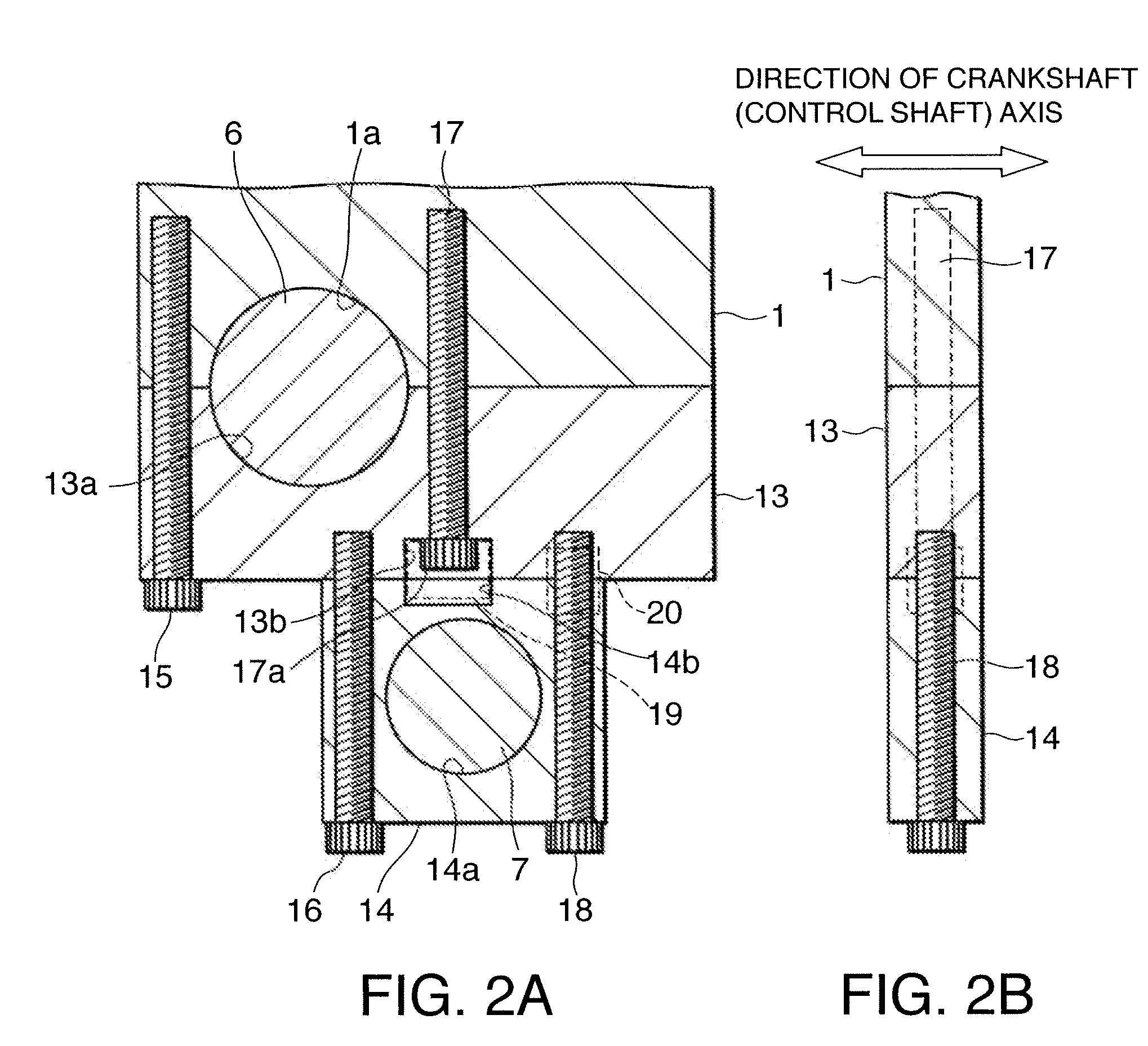
[0010]This structure causes a distance between the joint bolt located on the opposite side of the control shaft to the crankshaft and the extra bolt to increase such that the crankshaft bearing cap can be deformed easily when the internal combustion engine exerts a downward combustion load on the crankshaft. If the crankshaft bearing cap is deformed, a gap may be generated between the crankshaft bearing cap and the cylinder block.
[0013]It is therefore an object of this invention to improve a fixing structure for fixing the crankshaft bearing cap to the cylinder block in a double-link type variable-compression-ratio internal combustion engine.

Problems solved by technology

If such a requirement arises in the bearing structure according to the prior art, of the two joint bolts that secure the control shaft bearing cap to the crankshaft bearing cap, the joint bolt disposed between the crankshaft and the control shaft may interfere with the crankshaft.
If this is the case, to avoid interference with the crankshaft, the joint bolt cannot be allowed to penetrate the crankshaft bearing cap.
If the crankshaft bearing cap is deformed, a gap may be generated between the crankshaft bearing cap and the cylinder block.
The generation of a gap results in an excessive internal stress in the components of the bearing structure.
Further, joint surfaces of the crankshaft bearing cap and the cylinder block may suffer wear due to oscillation during stress, or in other words fretting wear.

Method used


Image

  • Bearing structure for variable-compression-ratio internal combustion engine
  • Bearing structure for variable-compression-ratio internal combustion engine
  • Bearing structure for variable-compression-ratio internal combustion engine

Examples


Embodiment Construction

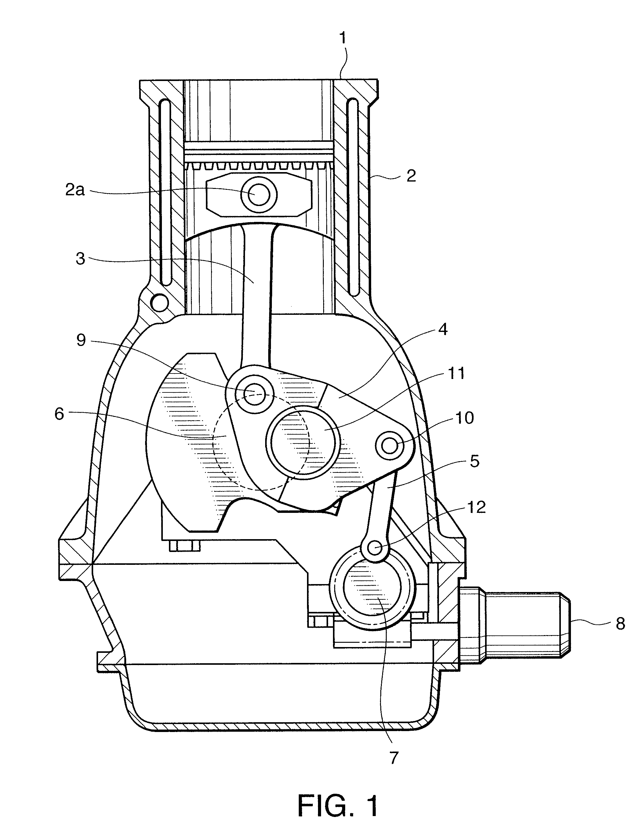
[0024]Referring to FIG. 1 of the drawings, a double-link type variable-compression-ratio internal combustion engine to which this invention is applied comprises a cylinder block 1. A cylinder is formed in the cylinder block 1 and a piston 2 is enclosed in the cylinder so as to slide axially within the cylinder. An end of an upper link 3 is connected to the piston 2 via a piston pin 2a. Another end of the upper link 3 connected to a lower link 4 via a connecting pin 9. The lower link 4 is connected to a crankshaft 6 via a crankpin 11.

[0025]According to the above construction, when the piston 2 slides in the cylinder up and down in the figure, the crankshaft 6 performs a rotational movement via the upper link 3 and the lower link 4.

[0026]The stroke range of the piston 2 within the cylinder varies depending on an angle subtended by the piston pin 2a and the crankpin 11 at the connecting pin 9.

[0027]To vary this angle, an end of a control link 5 is connected to the lower link 4 via a co...


PUM


Abstract

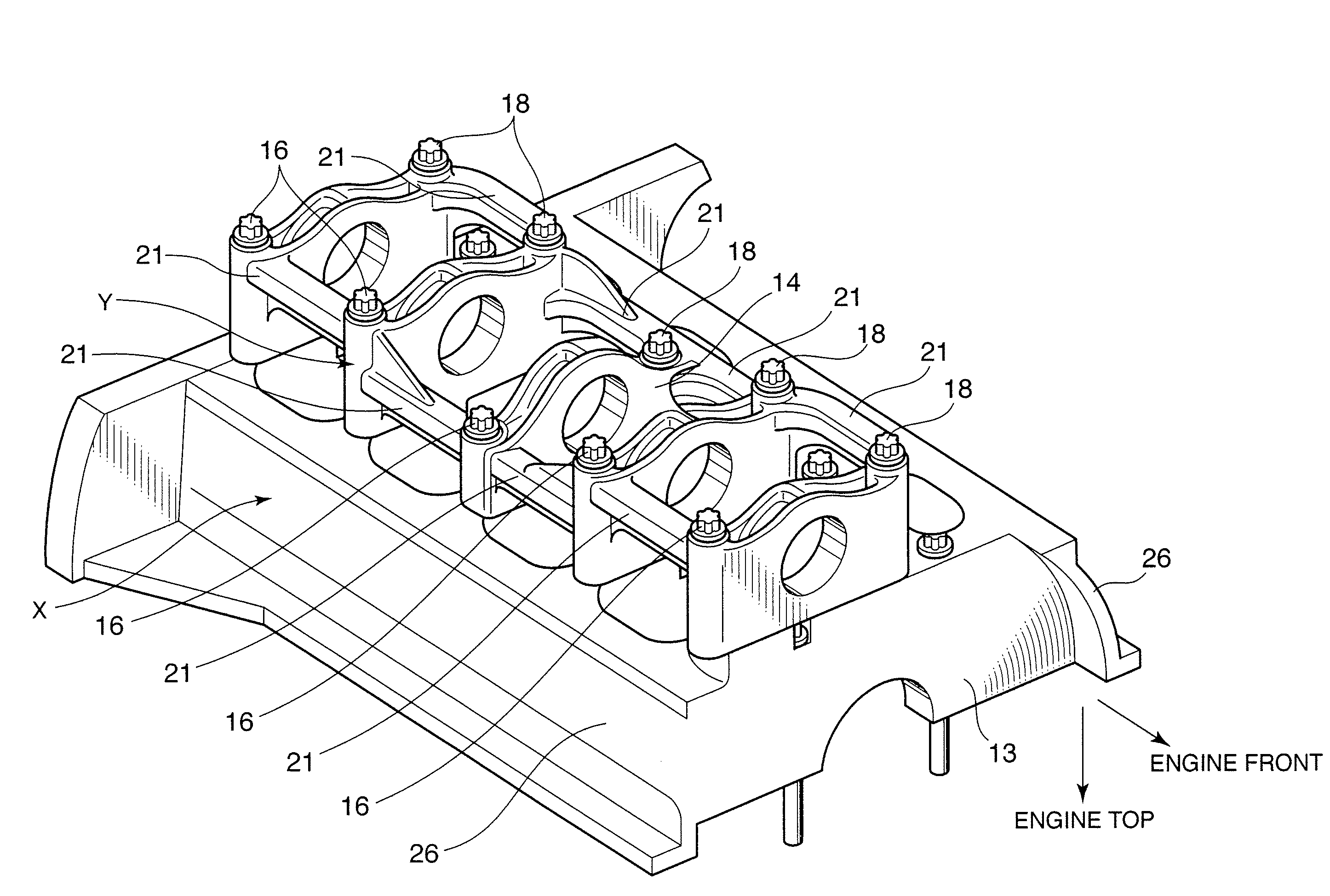
An internal combustion engine varies a compression ratio according to a rotational displacement of a control shaft which is connected to a crankshaft via links. A crankshaft bearing cap supporting the crankshaft in association with a cylinder block is fixed to the cylinder block by a first pair of joint bolts. A control shaft bearing cap which supports the control shaft is fixed to the crankshaft bearing cap by a second pair of joint bolts. A first joint bolt of the first pair of joint bolts, which is nearer to the control shaft, is disposed between the axes of the second pair of joint bolts. The supporting structure of the crankshaft is thereby enhanced.

Description

FIELD OF THE INVENTION[0001]This invention relates to a bearing structure for a double-link type variable-compression-ratio internal combustion engine in which a piston and a crankshaft are connected via plural links.BACKGROUND OF THE INVENTION[0002]JP2004-092448A, published by the Japan Patent Office in 2004, discloses a double-link type variable-compression-ratio internal combustion engine. The internal combustion engine comprises a piston and a crankshaft connected via an upper link and a lower link. An end of a control link is connected to the lower link. Another end of the control link is connected to a control shaft which is disposed in parallel with the crankshaft. When the control shaft performs a rotational displacement, the lower link rotates with respect to the crankshaft and a refracting angle between the upper link and the lower link varies such that a stroke range of the piston varies, bringing about a variation in the compression ratio of the internal combustion engin...

Claims


Application Information

Patent Timeline
IPC IPC(8): F16C9/02
CPCF02B75/048
Inventor TANAKA, YOSHIAKITAKAHASHI, NAOKITOMITA, MASAYUKI
Owner NISSAN MOTOR CO LTD
Learn More