
Method for computing drive currents for a plurality of leds in a pixel of a signboard to achieve a desired color at a desired luminous intensity

a technology of leds and leds, applied in the direction of cathode-ray tube indicators, static indicating devices, instruments, etc., can solve the problems of large number of connectors, insensitive human psycho-visual system to light intensity changes, and face exposure to significant heat loads

Active Publication Date: 2009-02-12
LANDMARK SCREENS
View PDF45 Cites 66 Cited by
  • Summary
  • Abstract
  • Description
  • Claims
  • Application Information

AI Technical Summary

Benefits of technology

"The present invention provides a method for computing drive currents for LEDs in a signboard to achieve a desired color at a desired luminous intensity. This method is particularly useful for signs with pixels made up of four or more primary colors. The method selects a number of colors within a color gamut and computes drive currents for the LEDs of each basis color to maximize the resulting luminous intensity of the selected color. The drive currents are then scaled to achieve the desired luminous intensity in the desired color. The method uses a constrained maximization technique, such as linear programming, and ensures that none of the drive currents is negative and each is less than a predetermined value. The technical effect of this invention is to provide a more efficient and effective way to achieve desired colors and luminous intensities in LED signs."

Problems solved by technology

In addition, the human psycho-visual system is insensitive to light intensity changes that are more rapid than about 100 Hz.
However, since each color in each pixel must be controlled independently of all others, large amounts of data must flow to each group of pixels whenever a change is made in the image displayed on the advertising structure.
Consequently, a large number of connectors are required for interconnecting components.
Additionally, particularly for structures exposed to strong sunlight, the faces may be also exposed to significant heat loads.
Therefore, cleaning the faces and controlling the thermal environment can prolong the life and reduce repair and maintenance costs.
As a result, the gamut available on a signboard may not be fully utilized.
The images shown thus may not have the attention-capturing or aesthetic impact that would be possible if the gamut were more effectively utilized.
A color perceived in a bright background looks different when the background brightness changes, so that some signboards may be difficult to read or an image appears to be of the wrong or unnatural colors under certain lighting conditions.

Method used


Image

  • Method for computing drive currents for a plurality of leds in a pixel of a signboard to achieve a desired color at a desired luminous intensity
  • Method for computing drive currents for a plurality of leds in a pixel of a signboard to achieve a desired color at a desired luminous intensity
  • Method for computing drive currents for a plurality of leds in a pixel of a signboard to achieve a desired color at a desired luminous intensity

Examples


Embodiment Construction

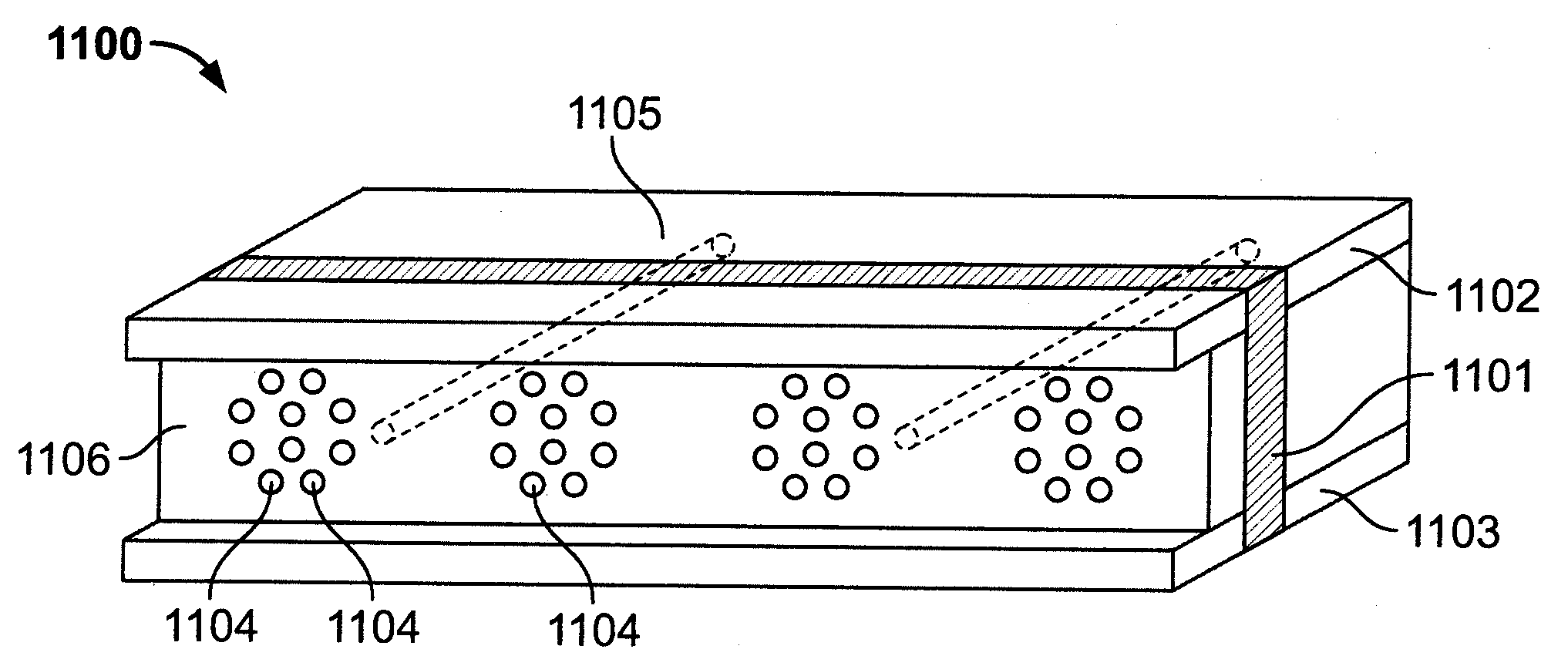
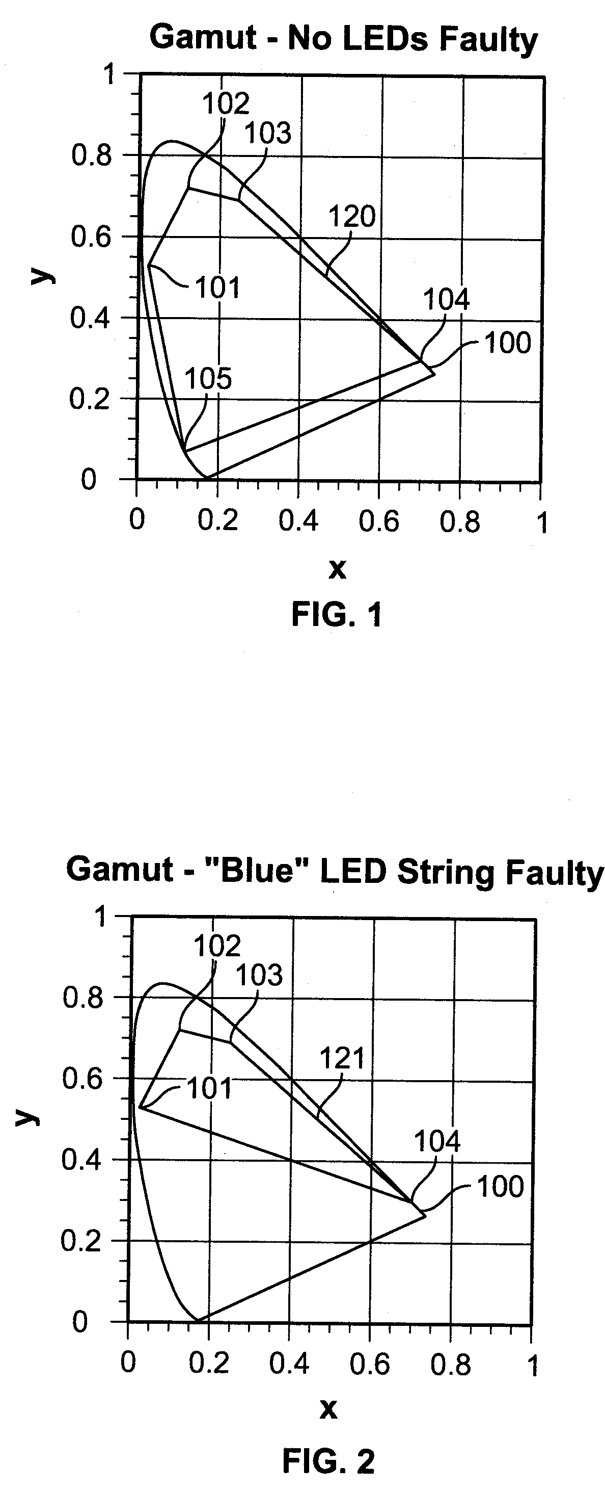
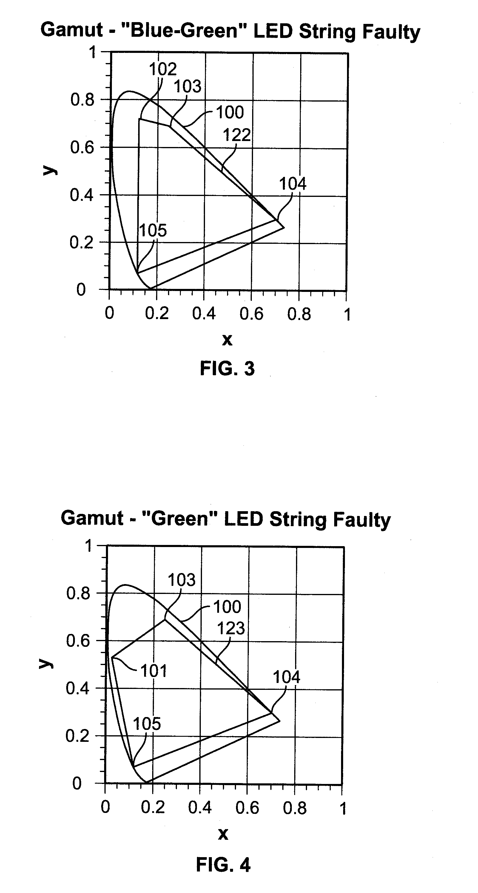
[0026]According to one embodiment of the present invention, a fault in an LED or the wiring in a pixel may be circumvented. When a fault in either an LED or in the wiring is detected and located, the intensities of other LEDs in a pixel may be dynamically altered, so that the pixel can continue to function based on other functional LEDs in the pixel, despite the fault and until repair is performed. Under this arrangement, the pixel may function with little or no noticeable difference from the input (original) tristimulus value for the pixel. In this embodiment, each pixel may have 3 or more different kinds of LED, with each LED providing light contributing to providing the color specified by the input (original) tristimulus value for the pixel coordinate (xi, yi). (The present detailed description follows the color coordinate convention of G. Wyszecki and W. Stiles, Color Science: Concepts and Methods, Quantitative Data and Formulae, 2nd Edition, John Wiley & Sons, Inc., New York (1...


PUM


Abstract

A method computes drive currents for LEDs in a pixel of a signboard to achieve a desired color at a desired luminous intensity. This method is particular applicable to a signboard having pixels made up of four (4) or more primary colors. The method selects a number of colors within a color gamut, and for each selected color, the method computes drive currents for the LEDs of each basis color, such that the resulting luminous intensity of the selected color is maximum. Using the computed drive currents, the method then scales the drive currents to achieve the desired luminous intensity in the desired color. The drive currents may be computed, for example, using a constrained maximization technique, such as linear programming. In one embodiment, the drive currents for each selected color are computed subject to the constraint that none of the drive currents is negative, and that their total is less than a predetermined value. In one embodiment, the selected color is expressed in the units of a linear color space.

Description

CROSS REFERENCE TO RELATED APPLICATIONS[0001]The present invention is also related to (a) U.S. Non-Provisional Patent Application, entitled “Method for Compensating for A Chromaticity Shift Due to Ambient Light in An Electronic Signboard,” filed herewith on the same day, bearing attorney docket number M-16380 US; (b) U.S. Non-Provisional Patent Application, entitled “Method for Fault-Healing in A Light Emitting Diode (LED) Based Display,” filed herewith on the same day, bearing attorney docket number M-16380-1D US; (c) U.S. Non-Provisional Patent Application, entitled “Method For Mapping A Color Specified Using A Smaller Color Gamut To A Larger Color Gamut,” filed herewith on the same day, bearing attorney docket number M-16380-2D US; (d) U.S. Non-Provisional Patent Application, entitled “Graphical Display Comprising a Plurality of Modules Each Controlling a Group of Pixels Corresponding to a Portion of the Graphical Display,” filed herewith on the same day, bearing attorney docket ...

Claims


Application Information

Patent Timeline
Patent Type & Authority Applications(United States)
IPC IPC(8): G09G3/32
CPCG09G3/14G09G3/2003G09G2320/0295G09G2320/0666G09G2300/0452G09G2330/10G09G2360/148G09G5/02G09G2320/0693
Inventor SCHEIBE, PAUL O.
Owner LANDMARK SCREENS
Learn More