Eureka AIR delivers breakthrough ideas for toughest innovation challenges, trusted by R&D personnel around the world.

Image encoding apparatus and image encoding method

a technology of image encoding and encoding methods, applied in the field of prediction encoding apparatuses, can solve problems such as inability to use methods, inability to use inter-frame prediction or intra-frame prediction, and inappropriate decision regarding inter-frame prediction or intra-frame prediction, and achieve the effect of efficient compression encoding

Inactive Publication Date: 2009-02-05
CANON KK
View PDF26 Cites 26 Cited by
  • Summary
  • Abstract
  • Description
  • Claims
  • Application Information

AI Technical Summary

Benefits of technology

The present invention provides an image encoding apparatus that can accurately predict and efficiently compress an image. It includes an intra-frame prediction unit to generate prediction errors and decode them to create reference pixels. A pixel selecting unit selects the reference pixels based on the intra-frame prediction errors and the input image. An intra-frame-prediction evaluation-value calculating unit calculates an evaluation value using the prediction errors and the input image. A determining unit uses the evaluation value to determine the encoding method for a block to be encoded. This invention allows for accurate prediction and efficient compression of images.

Problems solved by technology

However, for example, when encoding is to be executed in real time while shooting a moving picture using a video camera, the above method is so complex and resource intensive that it is difficult to use the method.
Therefore, if the techniques described in Japanese Patent Laid-Open No. 2005-244749 are used in H.264 encoding, problems arise because pixels are used that are different from the pixels that more favorably should be used.
This can result in an inappropriate decision regarding whether to use inter-frame prediction or intra-frame prediction.
An inaccurate decision regarding whether inter-frame prediction or intra-frame prediction should be used can reduce the quality of the compression encoding.
Furthermore, there exists a similar problem regarding selection between a plurality of prediction methods of intra-frame prediction encoding.
In contrast, in the case of compression at a high compression rate, where compression encoding typically causes much distortion, locally decoded pixels are considerably distorted relative to input pixels.
Therefore, where the determination regarding whether to use inter-frame prediction or intra-frame prediction is based on locally decoded pixels it has been difficult to generate optimal prediction errors.

Method used


Image

  • Image encoding apparatus and image encoding method
  • Image encoding apparatus and image encoding method
  • Image encoding apparatus and image encoding method

Examples


first embodiment

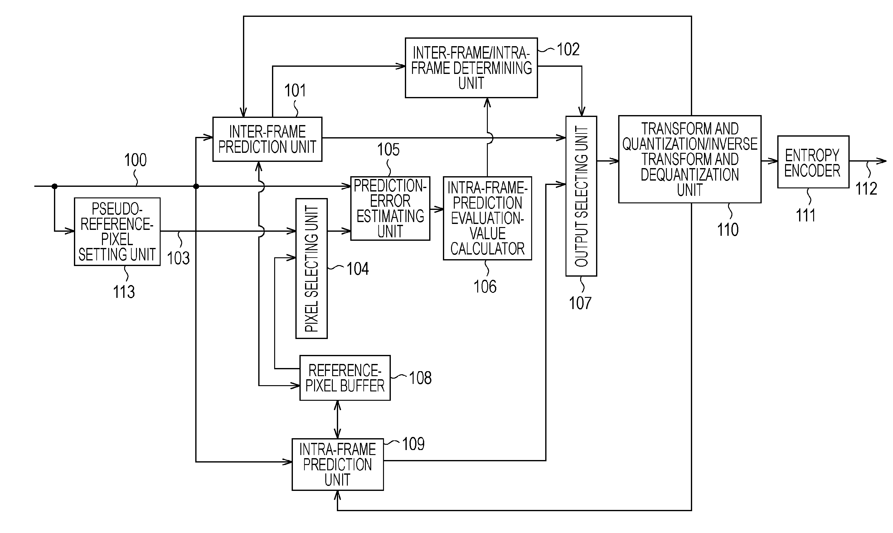
[0028]FIG. 1 is a block diagram showing an example functional configuration of an image encoding apparatus according to a first embodiment of the present invention. The first embodiment is described in the context of an example where image data yet to be encoded, representing an input image, is encoded according to the H.264 standard.

[0029]An inter-frame prediction unit 101 executes an inter-frame prediction operation regarding an input image 100 to output inter-frame prediction errors. An inter-frame / intra-frame determining unit 102 determines whether inter-frame prediction or intra-frame prediction is to be used for processing of a next macro block.

[0030]A pseudo-reference-pixel setting unit 113 sets arbitrary pseudo-reference-pixel signals 103 as values of pseudo reference pixels. For example, the pseudo-reference-pixel signals 103 may be signals representing a predetermined image or an image obtained by executing interpolation on the input image 100 or filtering the input image ...

second embodiment

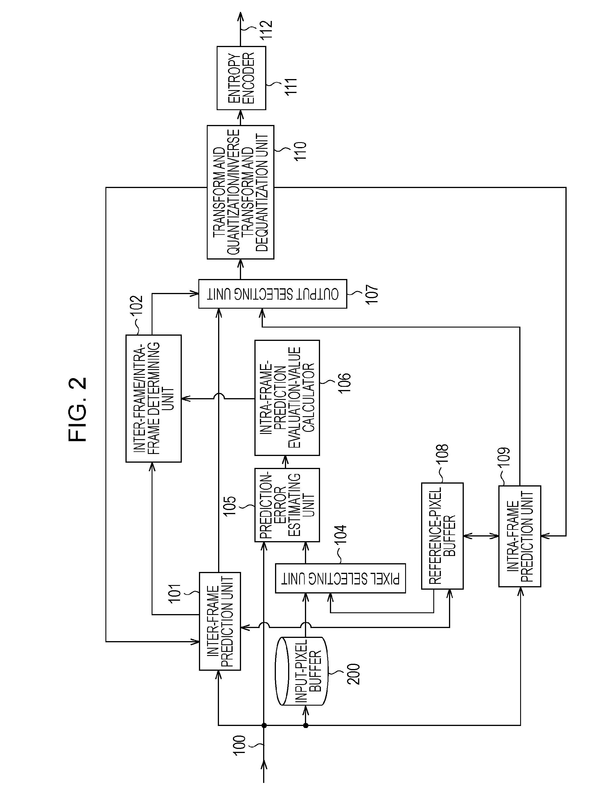
[0051]Next, a second embodiment of the present invention will be described with reference to FIG. 2. FIG. 2 is a block diagram showing an example of a functional configuration of an image encoding apparatus according to the second embodiment. In FIG. 2, 100 to 112 denote items corresponding to those denoted by the same numerals in the first embodiment described with reference to FIG. 1. In FIG. 2, 200 denotes an input pixel buffer that stores data corresponding to one macro block of the input image 100 and that outputs the data to the pixel selecting unit 104 after a delay corresponding to one macro block.

[0052]In this embodiment, when reference pixels are temporally available, the pixel selecting unit 104 outputs the reference pixels stored in the reference-pixel buffer 108, and when reference pixels are not available, the pixel selecting unit 104 outputs the data stored in the input pixel buffer 200.

[0053]The input pixel buffer 200 supplies to the pixel selecting unit 104 data of ...

third embodiment

[0055]Next, a third embodiment of the present invention will be described with reference to FIG. 8. FIG. 8 is an enlarged view of the left reference macro block 401a in this embodiment. Since the image encoding apparatus according to the third embodiment is configured the same as the image encoding apparatus according to the first embodiment, further description thereof is omitted.

[0056]In FIG. 8, reference marks 401a and 500 denote items corresponding to those denoted by the reference marks in FIGS. 4 and 5. A latest reference pixel 800 for which encoding and local decoding have been finished is illustrated in black. Pixels indicated in black and enclosed by a broken line 801 are pixels for which encoding and local decoding have not been finished. In this embodiment, as opposed to the second embodiment, when reference pixels are not available, the pseudo-reference-pixel setting unit 113 sets the latest locally decoded reference pixel as pseudo reference pixels. That is, the value o...


PUM


Abstract

In an image encoding apparatus including an intra-frame prediction unit that executes intra-frame prediction regarding an input image, when locally decoded pixels are not available, pseudo reference pixels are set to calculate an intra-frame-prediction evaluation value, and a method of encoding to be used for a block to be encoded is determined on the basis of the intra-frame-prediction evaluation value.

Description

BACKGROUND OF THE INVENTION[0001]1. Field of the Invention[0002]The present invention relates to image encoding apparatuses, image encoding methods, programs, and recording media. More specifically, the present invention relates to prediction encoding apparatuses.[0003]2. Description of the Related Art[0004]MPEG4 and H.264 are known as standards for compression encoding of macro blocks of moving-picture data using inter-frame and intra-frame correlations. In these standards, it is possible to achieve high-quality compression by using an inter-frame prediction method when temporal correlation between frames is high while using an intra-frame prediction method when correlation within a frame is high. Particularly, in the H.264 standard, a plurality of prediction units or a plurality of prediction modes is prepared for each of inter-frame prediction and intra-frame prediction so that methods of compression encoding are enhanced compared with those in MPEG4.[0005]The inter-frame predict...

Claims


Application Information

Patent Timeline
Patent Type & Authority Applications(United States)
IPC IPC(8): H04N7/32H04N7/26H04N19/102H04N19/50H04N19/107H04N19/117H04N19/134H04N19/137H04N19/176H04N19/503H04N19/593H04N19/80H04N19/91
CPCH04N19/00018H04N19/176H04N19/103H04N19/593H04N19/11H04N19/51
Inventor TANAKA, EIICHI
Owner CANON KK
Why Eureka
Eureka Blog
Learn More