Adapted method for spectrum management of digital communication systems

a digital communication system and spectrum management technology, applied in the field of digital communication system improvement methods and systems, can solve problems such as form spurious noise, interfere with intended transmissions, crosstalk effects in addition to long loop lengths, and achieve the main obstacles to reaching higher data rates

Active Publication Date: 2009-02-05
TELEFON AB LM ERICSSON (PUBL)
View PDF8 Cites 30 Cited by
  • Summary
  • Abstract
  • Description
  • Claims
  • Application Information

AI Technical Summary

Benefits of technology

[0024]4. placing constraints on power allocation of particular plurality of the communication lines between respective transmitter and receiver taking into consideration the determined line, signal and interference characteristi

Problems solved by technology

In turn, these crosstalk signals forms spurious noise that interferes with intended transmissions.
In general, crosstalk effects in addition to long loop lengths are the main obstacles to reaching higher data rates in such copper-based networks.
In some cases this interference can be 10 to 20 decibel larger than the background noise and has been identified by some as the dominant source of performance degradation in DSL systems.
Telephone companies are increasingly shortening the loop using remote terminal (RT) deployments, resulting in lower signal attenuation and larger available bandwidths.
Unfortunately this can cause other problems such as the “near far” effect due to the crosstalk.
In typical communication systems, interference limits each user's performance.
While long loop lengths certainly inhibit performance, the crosstalk problem has been recognized as the critical impairment with, for example, interference contributions of 10-20 dB over the background noise.
This process results in a fully distributed algorithm with a reasonable computational complexity.
Unfortunately this optimization is a difficult nonconvex problem.
Both of these algorithms are centralized and are not well-suited for practical implementation.
Unfortunately, many have shown that IWF can be far from optimal.

Method used


Image

  • Adapted method for spectrum management of digital communication systems
  • Adapted method for spectrum management of digital communication systems
  • Adapted method for spectrum management of digital communication systems

Examples


Embodiment Construction

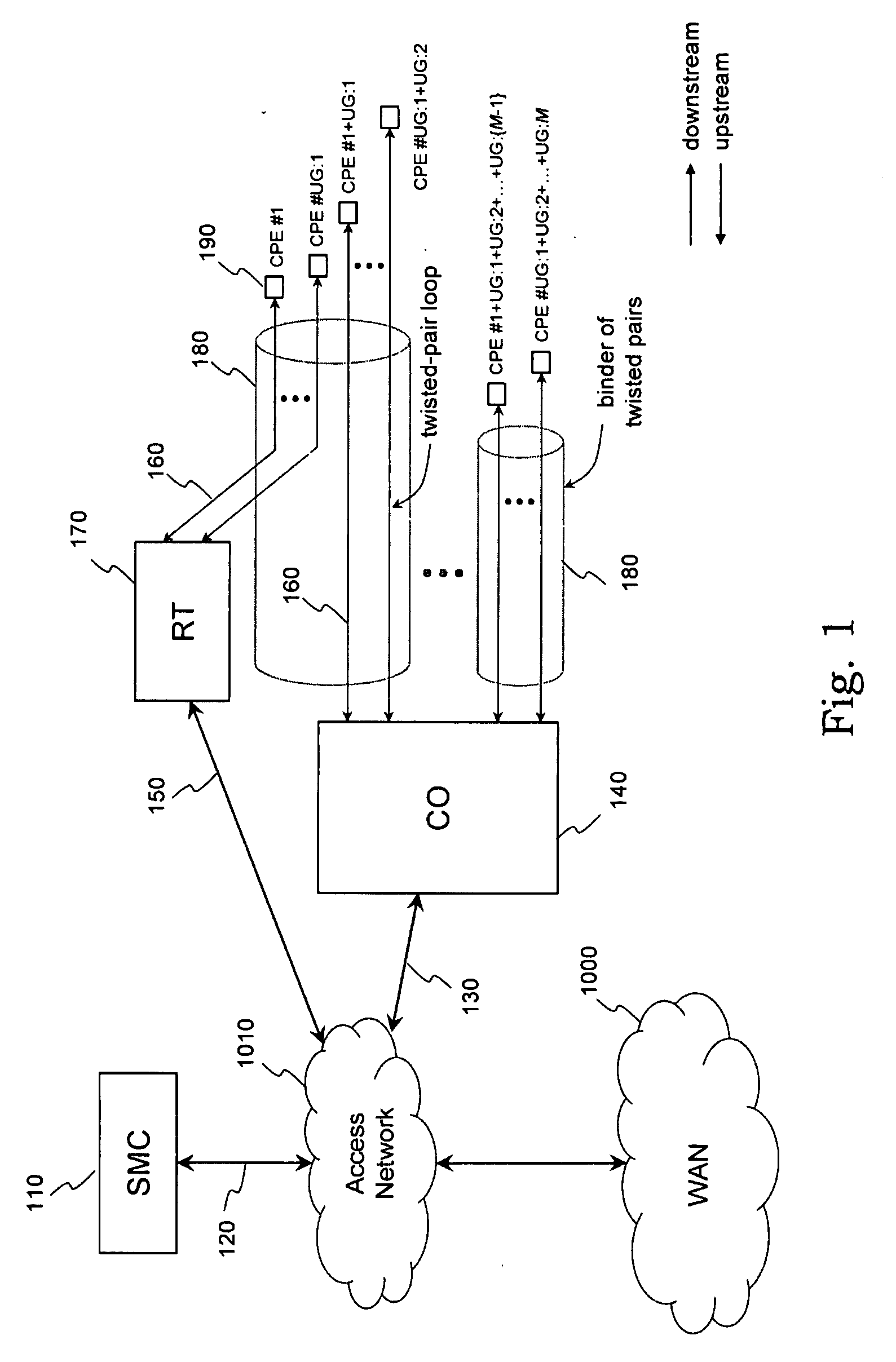
[0112]The present invention is described in connection with its preferred embodiment, namely as implemented into a multi-user digital subscriber line (DSL) system where discrete multitone (DMT) modulation is employed for communication between subscribers' customer premises equipment (CPE) and a central office (CO), and also between subscribers' CPE and remote terminals (RTs). These RTs are typically optical networking units (ONUs) or remote DSL access multiplexers (DSLAMs) deployed in modern DSL networks to shorten the length of copper twisted pair loops, with the aim of improving performance by decreasing the electrical signal attenuation on such lines. In the preferred embodiment, the said system will include an entity referred to as a spectrum management center (SMC) that coordinates the functions of one or more network elements (such as CPE, CO and / or RT) as described in detail below. In other embodiments, the SMC may directly control the functions of such network elements, or m...


PUM


Abstract

Provided is a method of determining a spectrum management of digital communication systems having a plurality of communication lines by determination of the power levels within each band, for each user, assuming a predetermined maximum interference from other users. The spectral management center has a power allocation determinator for receiving a modelled power level and a noise weight from each user communication line and is able to determine allocated power of its respective communication line based on the optimised determined power needs of the plurality of communication lines of the digital communication systems. In one form the calculations are undertaken in the SMC. In another form the master is undertaken in the SMC while the slave is undertaken at the user's modem and the power level of an individual communication line and its interference by adjacent lines is determined at the user's modem and communicated to the spectral management center.

Description

FIELD OF THE INVENTION[0001]The present invention relates to a method and system for improving digital communications systems. More specifically, the invention relates to dynamically determining operational parameters that affect performance in communication systems such as Digital Subscriber Line (DSL) systems. Still more particularly it relates to a method for distributed spectrum management of digital communication systems.BACKGROUND ART[0002]Digital subscriber line (DSL) technology can use the existing copper twisted pair networks used in the analog telephone network. The copper wiring is said to form communication lines or loops. At spaced ends of the communication lines are located transceivers (for example, modems) or other transmitters and receivers for respectively sending and receiving digital signals communicated along the loops.[0003]Twisted pairs are typically bundled together in a common physical sheath, known as a binder; all twisted pairs within a bundle are said to ...

Claims


Application Information

Patent Timeline
IPC IPC(8): H04J3/22
CPCH04J3/1694
Inventor EVANS, JAMIE SCOTTPAPANDRIOPOULOS, JOHN
Owner TELEFON AB LM ERICSSON (PUBL)
Why Eureka
Try Eureka