
Hybrid Display

a display and hybrid technology, applied in the field of displays, can solve the problems of large power consumption, easy burn-in, fragile lcd-based displays, etc., and achieve the effects of less blue resolution, reduced luminance, and increased brightness

Inactive Publication Date: 2009-02-05
NANOLUMENS ACQUISITION
View PDF0 Cites 27 Cited by
  • Summary
  • Abstract
  • Description
  • Claims
  • Application Information

AI Technical Summary

Benefits of technology

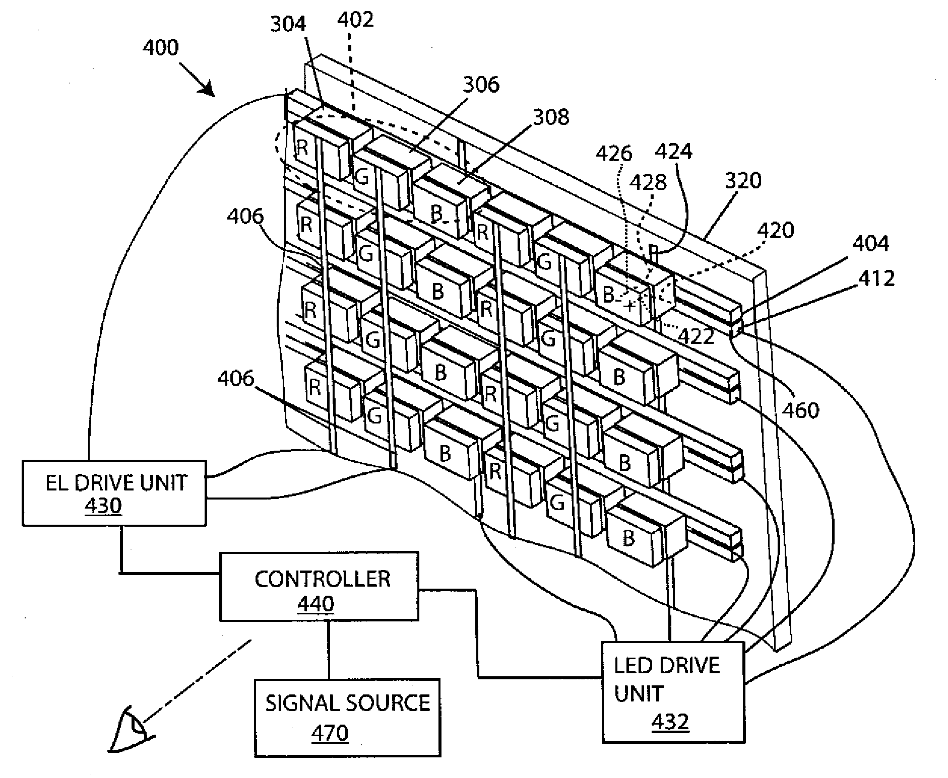
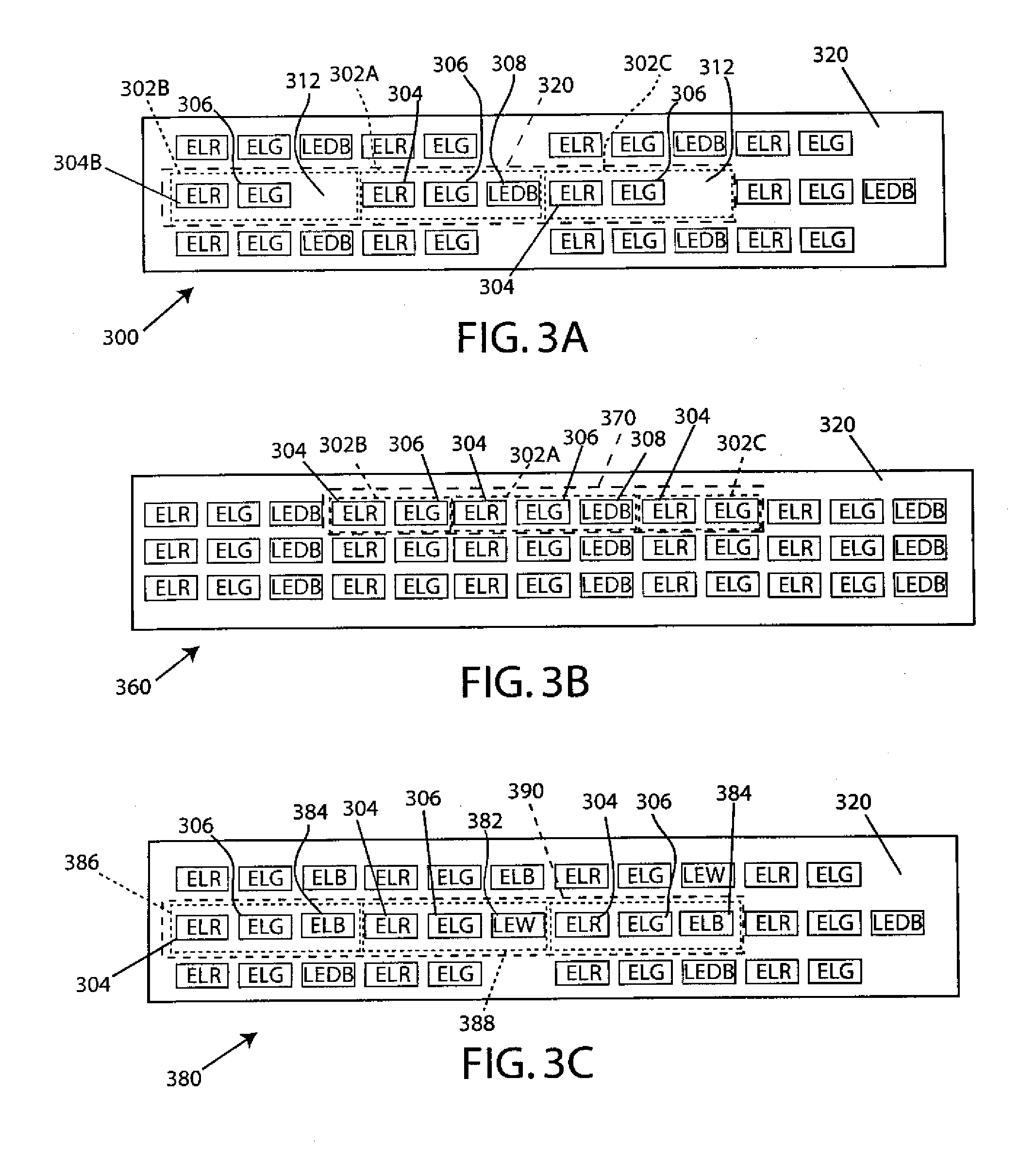
[0016]The dummy subpixel may assist in the proper spacing of the light emitter subpixels, such as when the light emitters are attached or embedded into a flexible substrate. For example, a dummy subpixel may occupy one of the subpixel locations of a pixel. An RGD pixel subpanel may be used in conjunction with a rear blue subpixel subpanel to create a panelized color display.
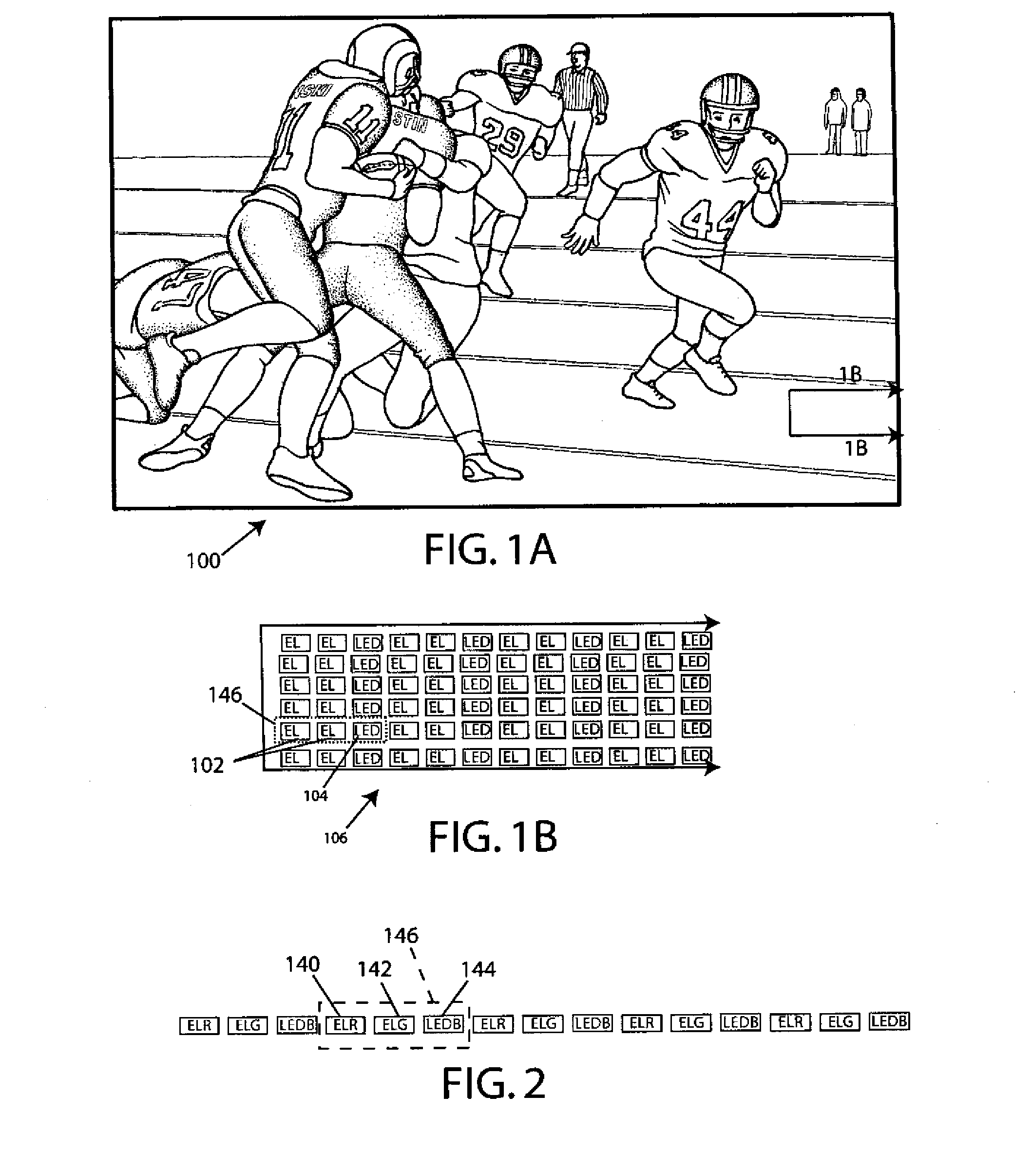
[0020]The present invention allows for the use of different type light emitter technologies to be used in a single display, thereby providing the ability to exploit the advantages of each light emitting technology. For example, by employing the SSTFEL or EL chips on a flexible substrate, lightweight, high brightness, and flexible characteristics are provided. By employing LEDs, increased brightness is provided without the large power demands of a full-color LED display. Furthermore, because fewer LEDs can be used to achieve the same level of brightness as a number of EL based subpixels, the driving of the LED is simplified and the power consumption of the display is decreased.

Problems solved by technology

For example, while plasma-based displays provide the advantages of high brightness, large viewing angle, and thin, light weight structures, they tend to require large amounts of power and are susceptible to burn-in.
LCD-based displays offer compact size and large viewing angles but are delicate and subject to trailing-effects when showing motion.
First, LCD and plasma displays do not lend themselves to scalability due to weight, cost, manufacturing, and efficiency issues.
Rigid displays do not offer the advantages of flexible displays.
While the aforementioned EL die-based display technologies provide the advantages associated with flexible displays, the absence of a bright blue phosphor has heretofore hindered the development of a full color flexible display.
While these prior art techniques provide displays of increased brightness they typically use a single light emitting technology and therefore are limited by the characteristics of the particular light-emitting technology employed.
Furthermore, these prior art displays are not flexible.

Method used


Image

  • Hybrid Display
  • Hybrid Display
  • Hybrid Display

Examples


Embodiment Construction

[0042]As required, exemplary embodiments of the present invention are disclosed herein. These embodiments are meant to be examples of various ways of implementing the invention and it will be understood that the invention may be embodied in alternative forms. The figures are not to scale and some features may be exaggerated or minimized to show details of particular elements, while related elements may have been eliminated to prevent obscuring novel aspects. Therefore, specific structural and functional details disclosed herein are not to be interpreted as limiting, but merely as a basis for the claims and as a representative basis for teaching one skilled in the art to variously employ the present invention.

[0043]For purposes of teaching and not limitation, the exemplary embodiments disclosed herein are discussed mainly in the context of EL die-based light emitter technologies such as SSTFEL and EL chip technologies that are used in conjunction with LED light emitters to form a hyb...


PUM


Abstract

In one embodiment, a hybrid display that may include a first light emitter of a first type and a second light emitter of a second type that define first and second addressable subpixels of a hybrid pixel. The first and second light emitters may be coupled to a support and provided with drive means for emitting light. The hybrid subpixels may be arranged in a variety of formats to provide a desired emission of light from the hybrid pixel. The support may be flexible to provide a flexible hybrid display. A dummy subpixel may be provided for spacing or to allow for transmission of light from another light emitter and light guides may be provided for guiding light to the dummy subpixel.

Description

FIELD OF THE INVENTION[0001]The present invention relates to displays, and more particularly to a flexible display with improved performance.BACKGROUND[0002]A variety of different display technologies have been developed, such as liquid crystal display (LCD), plasma, organic or polymeric light emitting diodes (LED), thick film dielectric electroluminescent (TDEL), and thin film electroluminescent (TFEL) technologies, to name a few. Each display technology has its own advantages and disadvantages. For example, while plasma-based displays provide the advantages of high brightness, large viewing angle, and thin, light weight structures, they tend to require large amounts of power and are susceptible to burn-in. LCD-based displays offer compact size and large viewing angles but are delicate and subject to trailing-effects when showing motion.[0003]Both LCD and plasma displays are rigid, relying on glass substrates. These rigid displays have some drawbacks. First, LCD and plasma displays...

Claims


Application Information

Patent Timeline
IPC IPC(8): G09G3/34
CPCG09G3/30G09G2300/0452G09G3/32
Inventor SILZARS, ARIS K.THOMAS, GARY E.
Owner NANOLUMENS ACQUISITION
Learn More