
Dual Door Release Handle

a technology of release mechanism and door handle, which is applied in the field of doors, can solve the problems of inconvenient operation, time-consuming and inconvenient for the operator, and the inability to easily reach the extension, etc., and achieves the effect of preventing a partially opened (unlatched) position, and preventing the operator from extending

Inactive Publication Date: 2009-02-05
SAF T CAB
View PDF57 Cites 7 Cited by
  • Summary
  • Abstract
  • Description
  • Claims
  • Application Information

AI Technical Summary

Benefits of technology

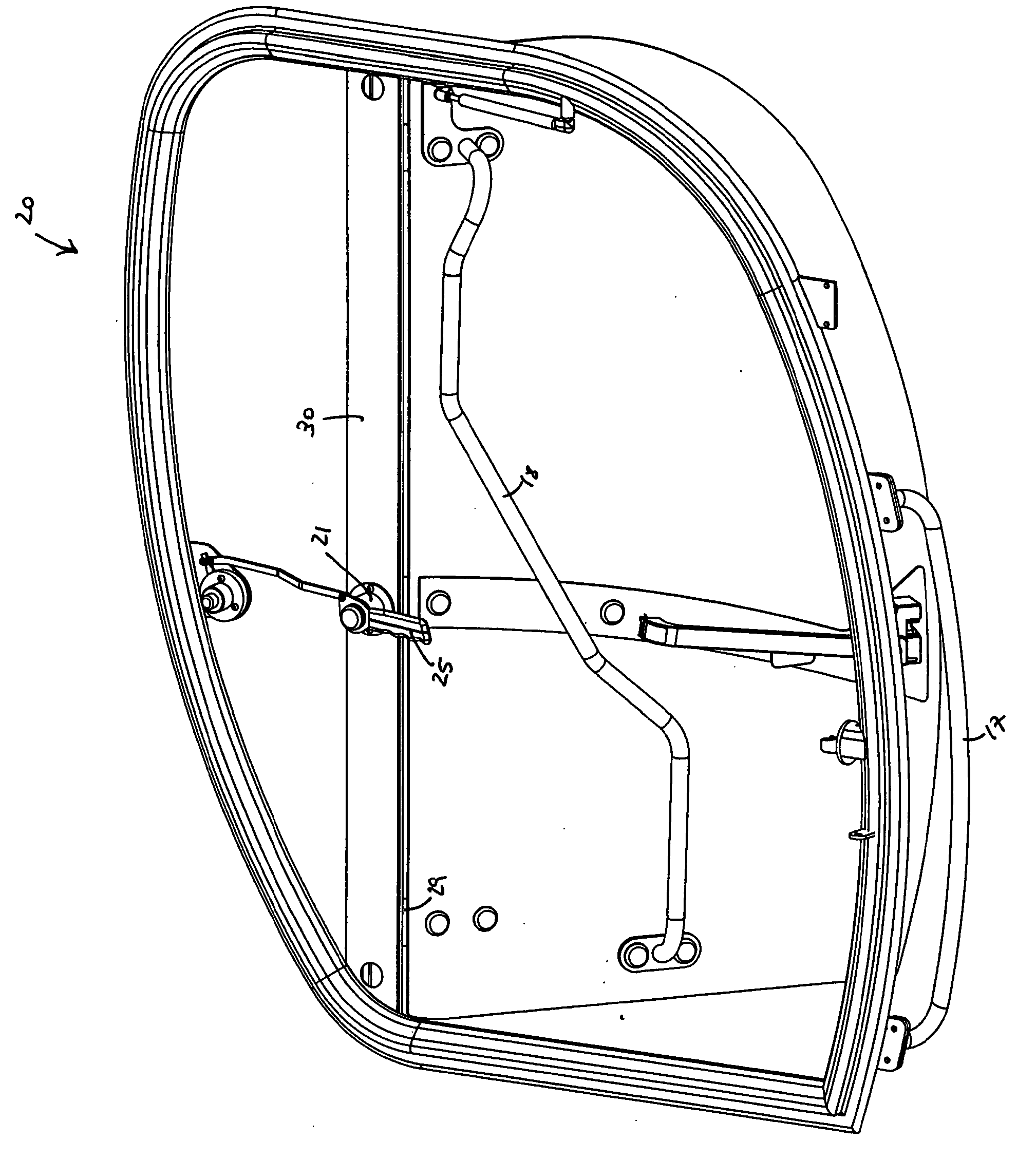
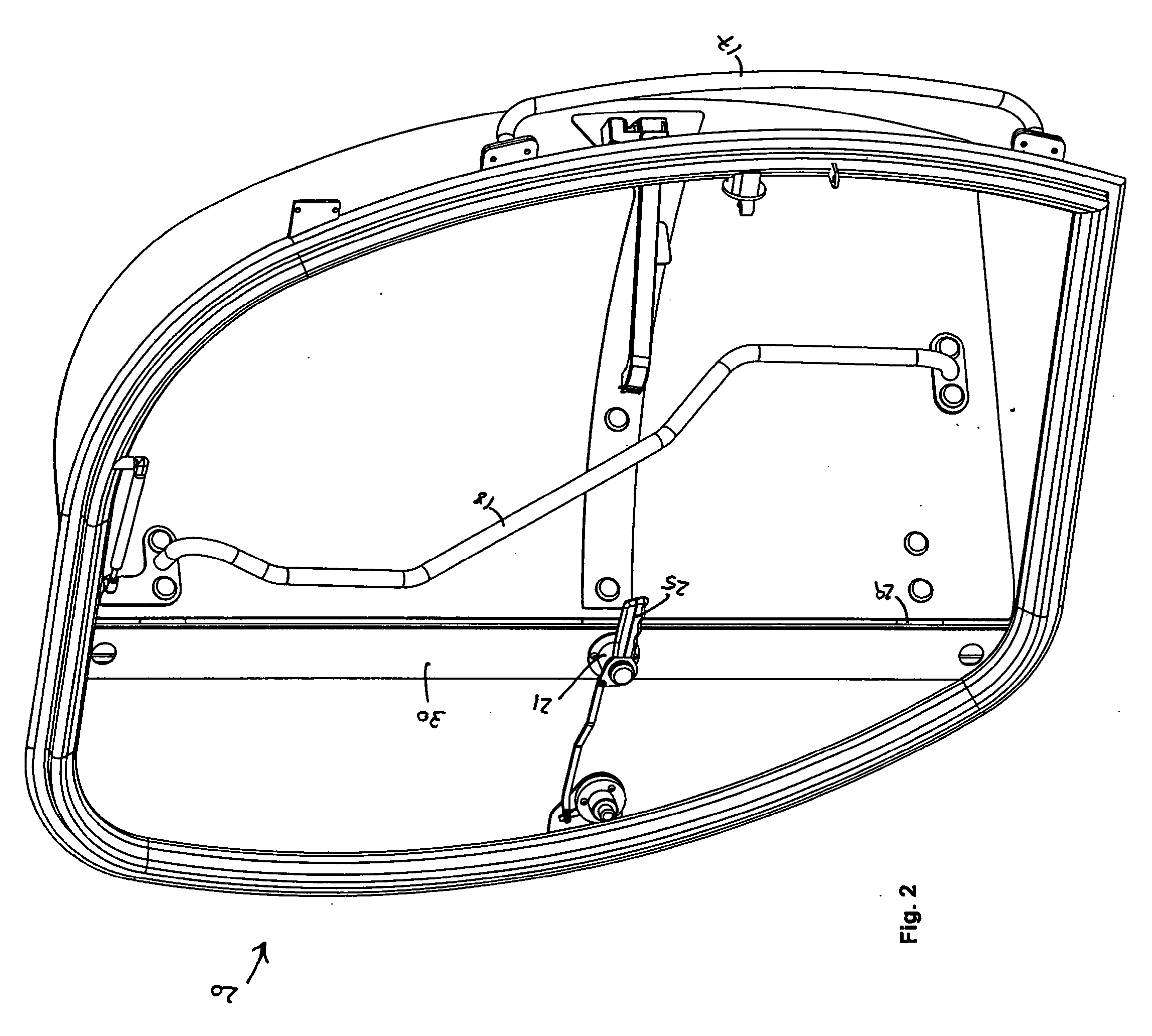
[0011]The present invention provides a dual door release handle and related mechanisms for use with cabs of industrial vehicles that an operator may reach from outside of such a cab in order to fully release a door that has been propped open in order to close it. The dual door release handle of the present invention includes a latching mechanism having a handle mounted on the inside of the cab that extends into the doorway such that it may be reached through the open door of the cab by an operator who is located outside and below the cab. The handle is primarily used to open the cab door from the inside. However, a linkage is provided between this handle and a lever or other operable device associated with a door holdback release mechanism inside the cab. The linkage is operatively attached to the handle and to the release mechanism such that turning the handle causes the linkage to move the release mechanism. Downward movement on the handle pulls the linkage and releases the door holdback that is holding the open door against the side of the cab. An operator inside the cab may operate the handle or the holdback release mechanism to release the door for closing. In addition, the present invention allows an operator outside of the cab to reach up into the cab from the outside and pull down on the interior handle in order to release the door from the holdback against the side of the cab allowing the door to swing freely so that it may be closed.
[0012]The latching mechanisms of the present invention also include a latch bolt assembly that is attached to the cab that stops progress of the door at a given position while it is being opened, but does not stop the door while it is being closed. These assemblies are operatively connected to the interior handle and to a latch bolt that protrudes to the exterior of the cab. A spring or other biasing means in the assembly causes the latch bolt to extend out when at rest. These assemblies are designed such that moving the interior handle a very short distance is sufficient to fully retract the latch bolt, which extends back out when the handle is released. The latch bolts of the present invention works in conjunction with corresponding cams with stops that are mounted on the cab door to stop the outward (opening) swinging motion of the door at a particular point, but do not stop the door while it is being closed. The stopping point may be any suitable location that allows the door to be sufficiently opened so that an operator may enter, and is determined by the position of the stop on the cam.

Problems solved by technology

It is time consuming and inconvenient for the operator to have to climb back up into the cab, and to operate two separate mechanisms just to close the door.
However, the extension cannot easily be reached when the door is latched in the open position since at such times the extension is sandwiched between the door and the side of the cab.
In addition, nothing in this patent provides an intermediate stopping position, or otherwise prevents a partially opened (unlatched) door from swinging completely open and latching in a full open position against the side of the cab.

Method used


Image

  • Dual Door Release Handle
  • Dual Door Release Handle
  • Dual Door Release Handle

Examples


Embodiment Construction

[0037]It is to be understood that while the following description of the present invention is based on the exemplary illustrated embodiments, the scope of the invention is not limited to this description, the illustrations, nor any of the particular locations or combinations depicted, but may be installed in various alternative locations, and in various alternative combinations, without affecting the scope or functionality thereof. Referring then to the exemplary embodiments illustrated in the drawings wherein like reference characters designates like or corresponding parts throughout the several views, and referring particularly to FIGS. 1-2 and 7-8, it is seen that the invention includes a latching mechanism 21 attached to a cross member 30 on a vehicle cab door frame 40 supporting a handle 25. Cross member 30 may be vertically or horizontally oriented, or may be part of the wall of the cab 20. Cab door 50 is attached via hinges 29 to cross member 30. Hand rails such as those illu...


PUM


Abstract

The present invention is a dual door release handle and related mechanisms for use with cabs of industrial vehicles that an operator may reach from outside of such a cab in order to fully release a door that has been propped open in order to close it. The dual door release handle of the present invention includes a latching mechanism having a handle mounted on the inside of the cab that extends into the doorway such that it may be reached through the open door of the cab by an operator who is located outside and / or below the cab. A linkage is provided between this handle and an operable device associated with the release mechanism inside the cab. The linkage is operatively attached to the handle and to the release mechanism such that turning the handle causes the linkage to move the release mechanism. Movement of the handle pulls the linkage and releases the holdback holding the open door against the side of the cab. Thus, an operator may reach up into the cab from the outside and pull down on the interior handle in order to release the door from its holdback position against the side of the cab allowing the door to swing freely so that it may be closed.

Description

[0001]This application claims the benefit of U.S. Provisional Application Ser. No. 60 / 963,254 filed on Aug. 2, 2007 which is incorporated herein by this reference.BACKGROUND OF THE INVENTION[0002]1. Field of the Invention[0003]The present invention relates to doors for operator compartments of industrial vehicles, and more specifically to a new and improved dual action door handle and release mechanism that can be used for one or both of (a) allowing a door of a cab of an industrial vehicle to be released from an intermediary position so that it may be swung wide open, and / or (b) releasing such a door that has been propped wide open so that it may be easily closed, both operations being possible from inside or outside of the cab.[0004]2. Description of the Prior Art[0005]Vehicles, particularly industrial vehicles, ordinarily include an operator compartment or cab which contains a seat for the operator, and controls for operating the vehicle. Cabs are often enclosed for safety reason...

Claims


Application Information

Patent Timeline
IPC IPC(8): E05C3/16E05C3/00
CPCE05C17/025E05C17/46E05Y2600/10E05Y2201/224E05D11/06Y10T292/096Y10T292/1047Y10T292/1078
Inventor ANTONETTI, THOMAS
Owner SAF T CAB
Learn More