Ejection failure mechanism

a failure mechanism and ejection technology, applied in the field of computer systems, can solve the problems of frustrating and complex process of configuration of computer system(s) (e.g., static and/or dynamic), and achieve the effect of facilitating the ejection of ejectable resources

Active Publication Date: 2009-01-29
MICROSOFT TECH LICENSING LLC
View PDF16 Cites 1 Cited by
  • Summary
  • Abstract
  • Description
  • Claims
  • Application Information

AI Technical Summary

Benefits of technology

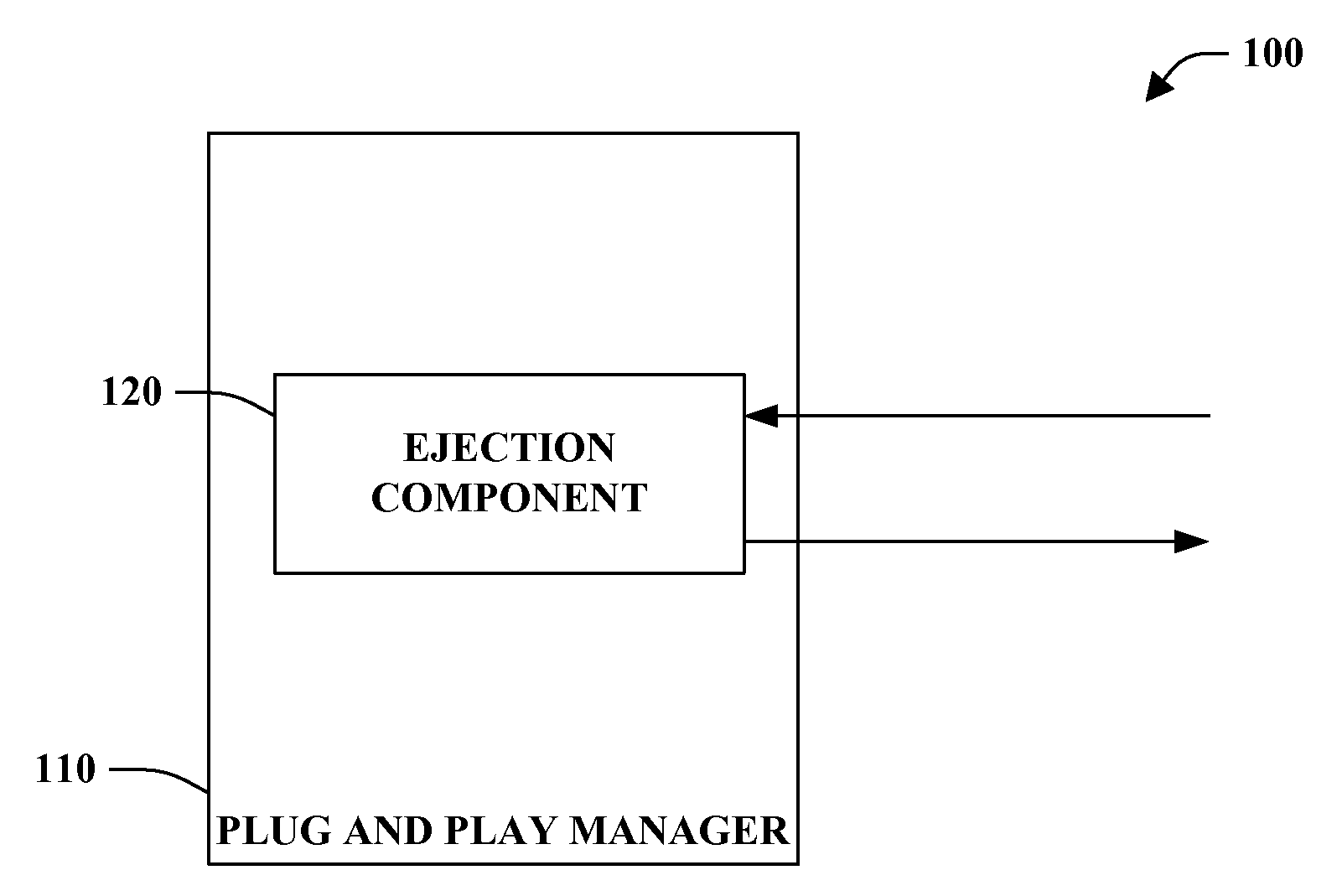
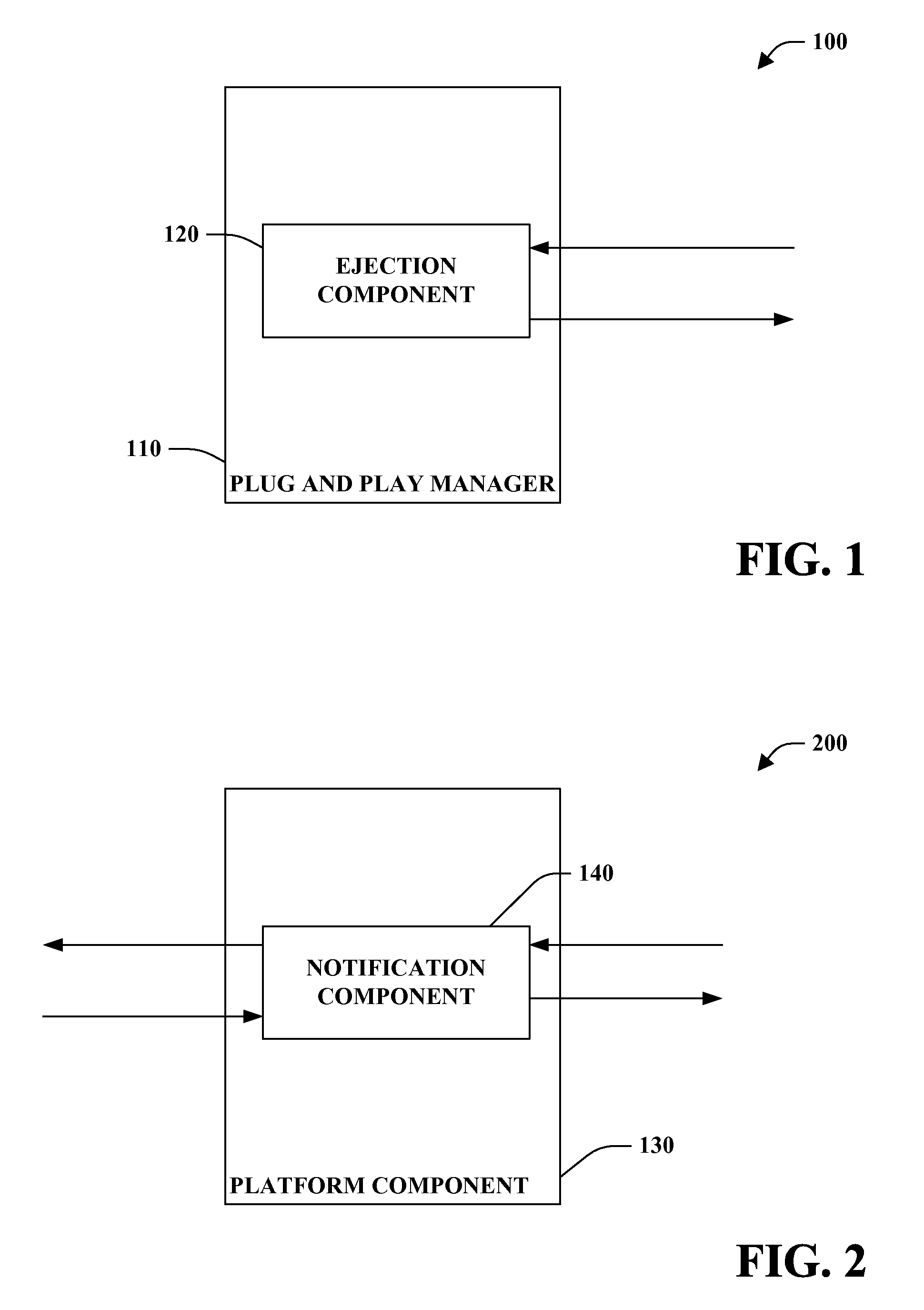
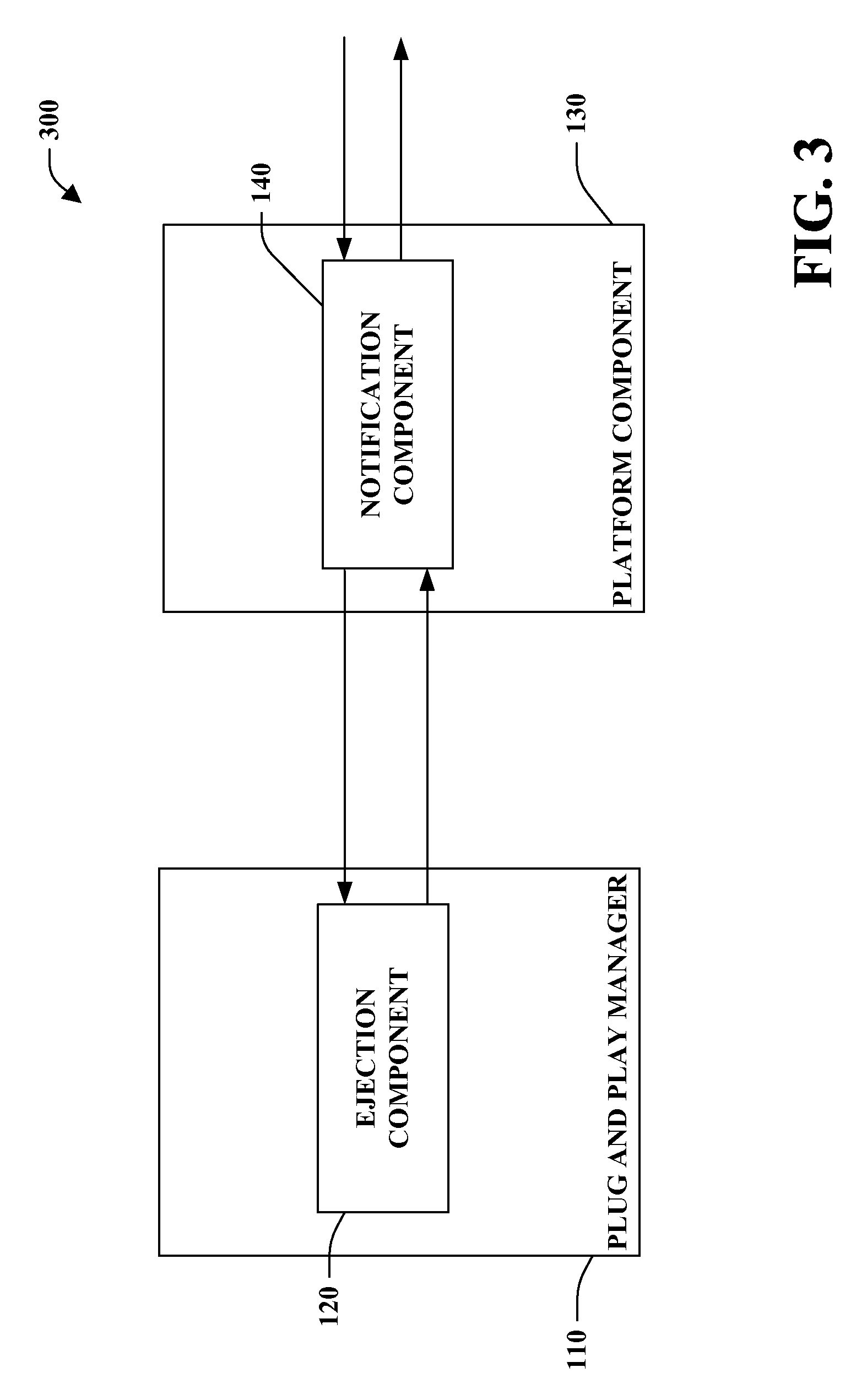
[0012]The system receives a request to eject an ejectable resource and provides information associated with a failure of the ejection of the ejectable resource, if ejection of the ejectable resource is unsuccessful. The system facilitates communication of information associated with the failure of the request to eject the ejectable resource, for example, to firmware (e.g., BIOS) of a computer system (not shown). In one example, the system is a component of an operating system kernel (not shown). The system thus mitigates limitation(s) of conventional system(s) (e.g., based on ACPI 2.0) which fail to provide meaningful information associated with ejection failure(s).
[0014]The plug and play manager manages ejectable resource(s). For example, the plug and play manager can load device driver(s) associated with the ejectable resource(s) and other device(s). The plug and play manager can further manage access to the ejectable resource(s).
[0015]The ejection component facilitates ejection of ejectable resource(s) based, at least in part, upon receipt of a request to eject the removable medium. The request can be received from a notification component of a platform component (not shown) (e.g., firmware and / or BIOS). For example, a management interface (not shown) can initiate the request by causing a Notify (3) to be invoked by the OSPM on the targeted ejectable resource.
[0023]The management console facilitates management of the system. For example, the management console can comprise input device(s) and / or output device(s). Administrator(s) and / or user(s) of the system can receive information and / or provide information via the management console.

Problems solved by technology

Configuration of computer system(s) (e.g., static and / or dynamic) can be a frustrating, complex process.

Method used


Image

  • Ejection failure mechanism
  • Ejection failure mechanism
  • Ejection failure mechanism

Examples


Embodiment Construction

[0036]The present invention is now described with reference to the drawings, wherein like reference numerals are used to refer to like elements throughout. In the following description, for purposes of explanation, numerous specific details are set forth in order to provide a thorough understanding of the present invention. It may be evident, however, that the present invention may be practiced without these specific details. In other instances, well-known structures and devices are shown in block diagram form in order to facilitate describing the present invention.

[0037]As used in this application, the term “computer component” is intended to refer to a computer-related entity, either hardware, a combination of hardware and software, software, or software in execution. For example, a computer component may be, but is not limited to being, a process running on a processor, a processor, an object, an executable, a thread of execution, a program, and / or a computer. By way of illustrat...


PUM


Abstract

A system and method for an ejection failure mechanism is provided. The system receives a request to eject an ejectable resource, and, provides information associated with a failure of the ejection of the ejectable resource, if ejection of the ejectable resource is unsuccessful. The system thus provides a deterministic mechanism through which information associated with failure of the ejection of an ejectable resource can be communicated. As such, an initiator of the request to eject can receive information associated with a cause of the ejection failure.

Description

CROSS-REFERENCE TO RELATED APPLICATIONS[0001]This application is a continuation of U.S. patent application Ser. No. 10 / 405,726, filed Apr. 2, 2003 and entitled EJECTION FAILURE MECHANISM, the entirety of which is incorporated herein by reference.TECHNICAL FIELD[0002]The present invention relates generally to computer system(s) and, more particularly, to an ejection failure mechanism for ejectable resource(s) of computer system(s).BACKGROUND OF THE INVENTION[0003]Configuration of computer system(s) (e.g., static and / or dynamic) can be a frustrating, complex process. Computer systems range from relatively simple systems to multi-processor complex systems. For example, high-end servers can include a plurality of hot-pluggable resource(s), a service processor and / or a management console. The service processor and / or the management console can control hardware that is visible to an Operating System-directed Configuration and Power Management system (“OSPM”). Typical scenarios include dyn...

Claims


Application Information

Patent Timeline
Patent Type & Authority Applications(United States)
IPC IPC(8): G06F9/44G06F9/445
CPCG06F9/445
Inventor GLASS, ADAM B.OSHINS, JACOB
Owner MICROSOFT TECH LICENSING LLC
Why Eureka
Try Eureka