
Method for Real-Time Estimation of Engine Combustion Parameters from Vibratory Signals

a technology of vibratory signals and engine combustion parameters, which is applied in the direction of machines/engines, electric control, instruments, etc., can solve the problems of inability to be standardized in vehicles, the engine has become an assembly of complex systems, and the extraction of coherent combustion parameters from an accelerometer is difficul

Inactive Publication Date: 2009-01-29
INST FR DU PETROLE
View PDF19 Cites 22 Cited by
  • Summary
  • Abstract
  • Description
  • Claims
  • Application Information

AI Technical Summary

Benefits of technology

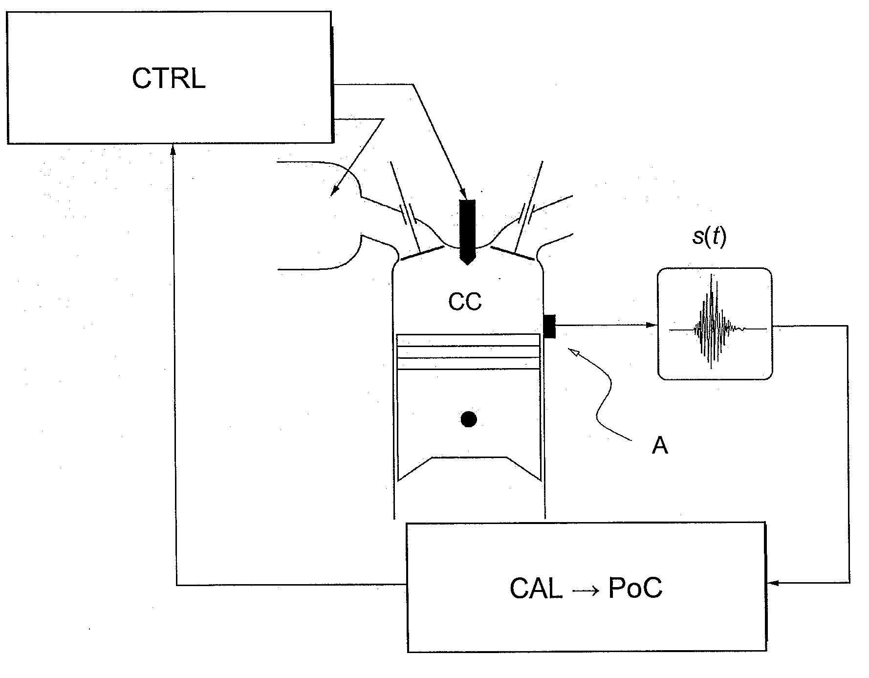
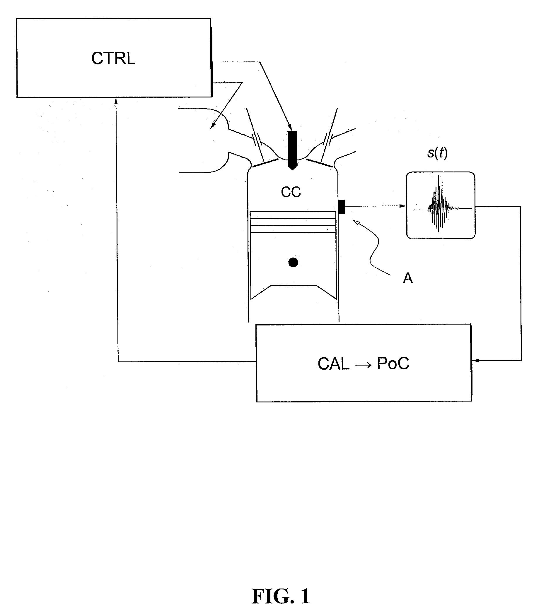
[0032]Estimation of combustion parameters according to the invention can be used within the context of combustion control of an internal-combustion engine.
[0033]The

Problems solved by technology

In this context, the engine has become an assembly of complex systems requiring management by means of modern automation techniques.
This method allows direct access to physical combustion parameters but, because of the life and cost of this type of detectors, they cannot yet be standard in vehicles.
Extraction of coherent combustion parameters from an accelerometer is difficult because of the nature of the signal that is delivered.
The parameters from the aforementioned approaches cannot be used directly for applications linked with internal-combustion engine diagnosis and control.
Their field of application is therefore limited.

Method used


Image

  • Method for Real-Time Estimation of Engine Combustion Parameters from Vibratory Signals
  • Method for Real-Time Estimation of Engine Combustion Parameters from Vibratory Signals
  • Method for Real-Time Estimation of Engine Combustion Parameters from Vibratory Signals

Examples


application example

[0145]The performances of the invention are illustrated through an application to a diesel engine operating in HCCI mode. For didactic reasons, the example focuses on a single cylinder, but the method can be readily generalized to multicylinder engines. The goal of this example is to show the pertinence of parameters PoC from the Fourier observer by comparing them with parameters obtained from the analysis of the cylinder pressure signal. The control of the mass injected during the pilot injection is also presented and the goal of this strategy is to reduce the noise level of the engine.

[0146]Observer Calibration

[0147]Table 1, where Ncyl represents the number of cylinders of the engine, shows the values of the parameters required for calibration of the Fourier observer.

TABLE 1Summary of the adjustment parameters suited to the test engineParameterUnitDescriptionValue1degreelower boundary of the angular−20window2degreeupper boundary of the angular50windowF1Hertzlower cut-off frequency...


PUM


Abstract

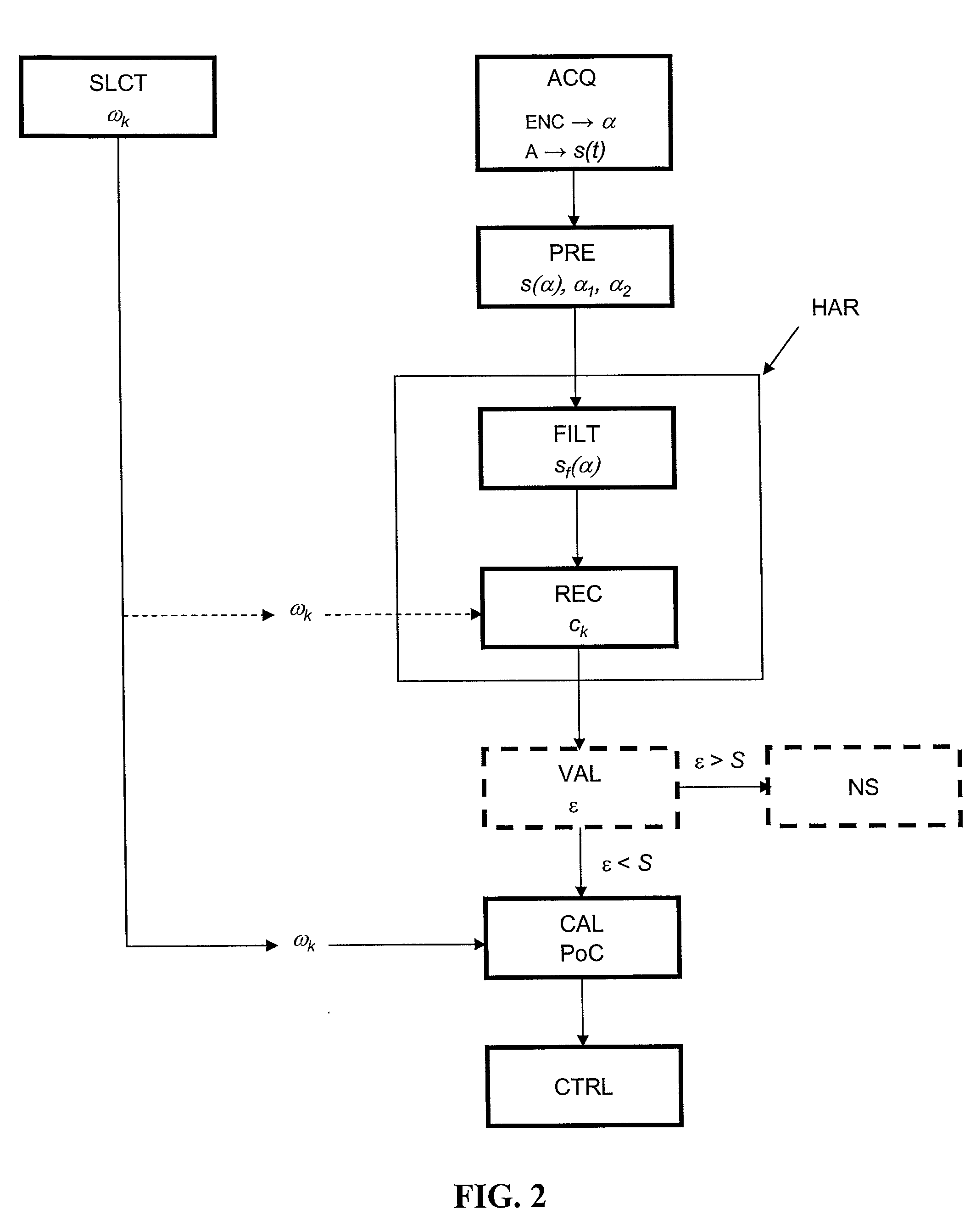
The invention relates to a method having application to combustion control of an internal-combustion engine for real-time estimation of engine combustion parameters from vibratory signals. A vibratory signal representative of the engine vibrations is continuously acquired as a function of the crank angle, from a vibration detector. Real-time filtering of this vibratory signal and real-time estimation of the Fourier decomposition coefficients for the acquired vibratory signal is carried out by inverting the dynamics of the filter which is used. Finally, real-time estimation of combustion parameters allowing the combustion to be qualified is carried out from these coefficients.

Description

BACKGROUND OF THE INVENTION[0001]1. Field of the Invention[0002]The present invention relates to a method for real-time estimation of combustion parameters of an internal-combustion engine from the vibratory response of the engine delivered by a vibration detector (accelerometer).[0003]2. Description of the Prior Art[0004]Standards for emission reduction have led to a progressive adaptation of engine technologies such as the introduction of additional actuators (exhaust gas recirculation valves, direct electronic injection and variable-geometry turbines) and new combustion modes (homogeneous diesel combustion or stratified gasoline combustion). In this context, the engine has become an assembly of complex systems requiring management by means of modern automation techniques. The engine control function manages the available actuators to guarantee engine performance while meeting environmental constraints. A fundamental aspect of engine control lies in the combustion control system v...

Claims


Application Information

Patent Timeline
IPC IPC(8): F02D45/00
CPCG01M15/12
Inventor CHAUVIN, JONATHANBENTOLINA, YOHANGRONDIN, OLIVIER
Owner INST FR DU PETROLE
Learn More