
Method for detecting an isolated network

Active Publication Date: 2009-01-29
SMA SOLAR TECH AG
View PDF10 Cites 16 Cited by
  • Summary
  • Abstract
  • Description
  • Claims
  • Application Information

AI Technical Summary

Benefits of technology

[0011]It is the object of the invention to indicate a method that reliably allows for detecting an isolated network, additional energy consumption for providing interruption-free current supply being intended to be as low as possible and unpleasant side effects such as component load or noise being avoided.
[0015]The method of the invention offers the advantage that the additional energy expense is at its lowest. There is no or only a low additional component load. Also, the method does not make any noise; existing algorithms for calculating the reactive power may be used; additional energy consumption for providing an interruption-free current supply is minimal; displacements of the zero crossing, which are e.g., caused by centralized ripple control signals do not lead to unintended isolated network detections. Also, it is not necessary to analyze several frequencies in terms of computation. As a result, the computing expense is minimal.
[0016]In an advantageous further development of the method of the invention, there is provided that the voltage amplitude of the test signal is smaller than 2% of the nominal voltage amplitude of the mains voltage. As a result, the additional energy need is minimized, with detection of an isolated network still being reliably performed.

Problems solved by technology

This results in a phase difference between the converter voltage and the mains voltage for a corresponding transient current to flow.
In connection with voltage controlled inverters, a varying phase difference results in undesired active power flows.
The method however needs a lot of computing time since the impedances are calculated by means of complex algorithms (e.g., FFT).
Impressing a periodical, pulse-shaped current makes however an unpleasant noise similar to the ticking of an alarm clock.
Moreover, in order to allow detecting properly the formation of an isolated network, high pulse currents are needed, which result in additional component load in the converter.
Additionally, the method is very sensitive if displacements of the zero crossing on the mains voltage are detected through centralized ripple control signals.

Method used


Image

  • Method for detecting an isolated network
  • Method for detecting an isolated network
  • Method for detecting an isolated network

Examples


Embodiment Construction

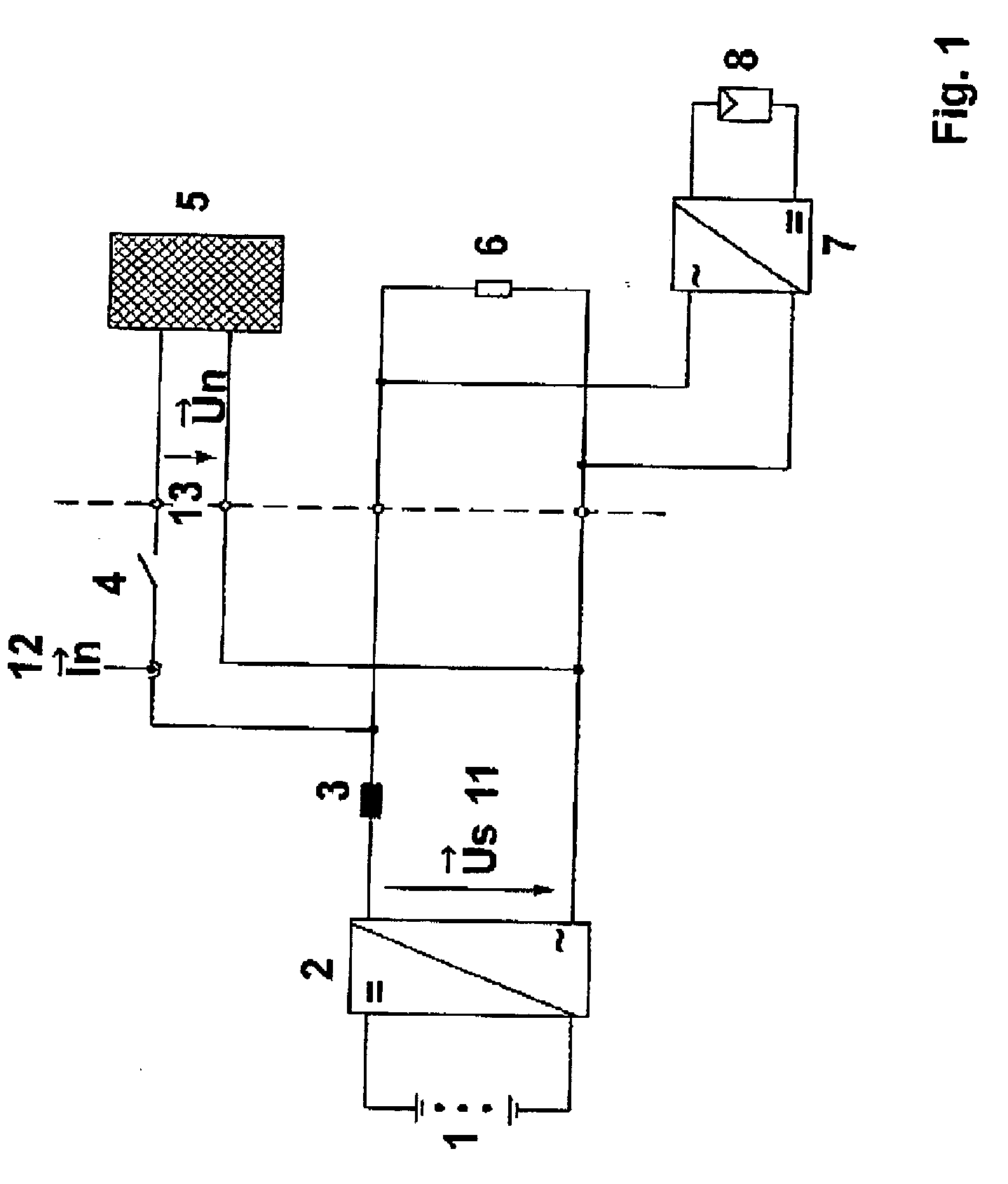
[0031]FIG. 1 shows an illustration of a circuit array with a battery inverter 2.

[0032]The circuit array constitutes a consumer generating system for electric energy. It not only includes the battery inverter 2, to which there is connected a rechargeable battery 1, but also a solar generator or a photovoltaic generator 8 with a second inverter 7 that is connected in parallel with the battery inverter. The battery inverter 2 has a choke 3 by which it is connected in parallel with a grid 5, a transfer contactor 4 being interposed therein between.

[0033]Instead of or in addition to the photovoltaic generator 8 and / or the battery, a wind power plant with PM generator, a speed variable internal combustion engine, a fuel cell or the like may be utilized. These are increasingly used for generating energy.

[0034]Special rates are often offered for such type consumer generation systems so that it is interesting for the operator of such plants to feed the generated current into the utility grid....


PUM


Abstract

The subject matter of the invention is a method for detecting an isolated network for an inverter (2) carrying a converter voltage that is adapted for connection in parallel with a grid (5) having a mains frequency and electric loads and that is decoupled from the grid (5) by a choke (3), a test signal being superimposed upon the converter voltage at a test frequency the frequency of which is smaller than the mains frequency, the amplitude of the test signal being much smaller than the nominal voltage amplitude of the mains voltage on the one side but still just large enough on the other side for changes in reactive power to be detectable as a result of the test signal, a reactive power share being determined, which oscillates with the test frequency, this share not being allowed to fall below an imposed minimum for an isolated operation to be reliably excluded.

Description

1. FIELD OF THE INVENTION[0001]The invention relates to a method for detecting an isolated network for an inverter carrying a converter voltage that is adapted for connection in parallel with a grid having a mains frequency and electric loads and that is decoupled from the grid by a choke.[0002]Special rates are often offered for such type customer generation systems so that it is of interest for the operator of such plants to feed the generated current into the utility grid. For operation in parallel with the utility grid, particular safety and connection conditions must be taken into consideration.[0003]Of particular interest is the existing grid monitoring. A consumer generation system must detect a failure of the utility grid and then suspend operation. It is not allowed to continue feeding the grid since a person performing maintenance works at the utility grid may get injured if a grid portion has been disconnected but the consumer generation system is still working in this po...

Claims


Application Information

Patent Timeline
IPC IPC(8): G01R21/00
CPCH02J2003/388H02J3/38H02J3/388
Inventor STRNAD, MICHAELBECHTEL, NEIDHARDTHARDT, CHRISTIAN
Owner SMA SOLAR TECH AG
Learn More