
Method and machine for producing three-dimensional objects by means of successive layer deposition

a three-dimensional object and successive layer technology, applied in the direction of turning machine accessories, drawing profiling tools, butter production, etc., can solve the problems of two types of materials being deposited the model using this type of device, and the time it takes to deposit the two types of materials one after the other, etc., to achieve the effect of rapid production of models

Inactive Publication Date: 2009-01-22
MARSAC NICOLAS
View PDF20 Cites 32 Cited by
  • Summary
  • Abstract
  • Description
  • Claims
  • Application Information

AI Technical Summary

Benefits of technology

[0012]The purpose of the invention is therefore to pr...

Problems solved by technology

The making of models using this type of device, depositing the two types of materials one after the other, is relatively long, namely several hours and even several days.

Method used


Image

  • Method and machine for producing three-dimensional objects by means of successive layer deposition
  • Method and machine for producing three-dimensional objects by means of successive layer deposition
  • Method and machine for producing three-dimensional objects by means of successive layer deposition

Examples


Embodiment Construction

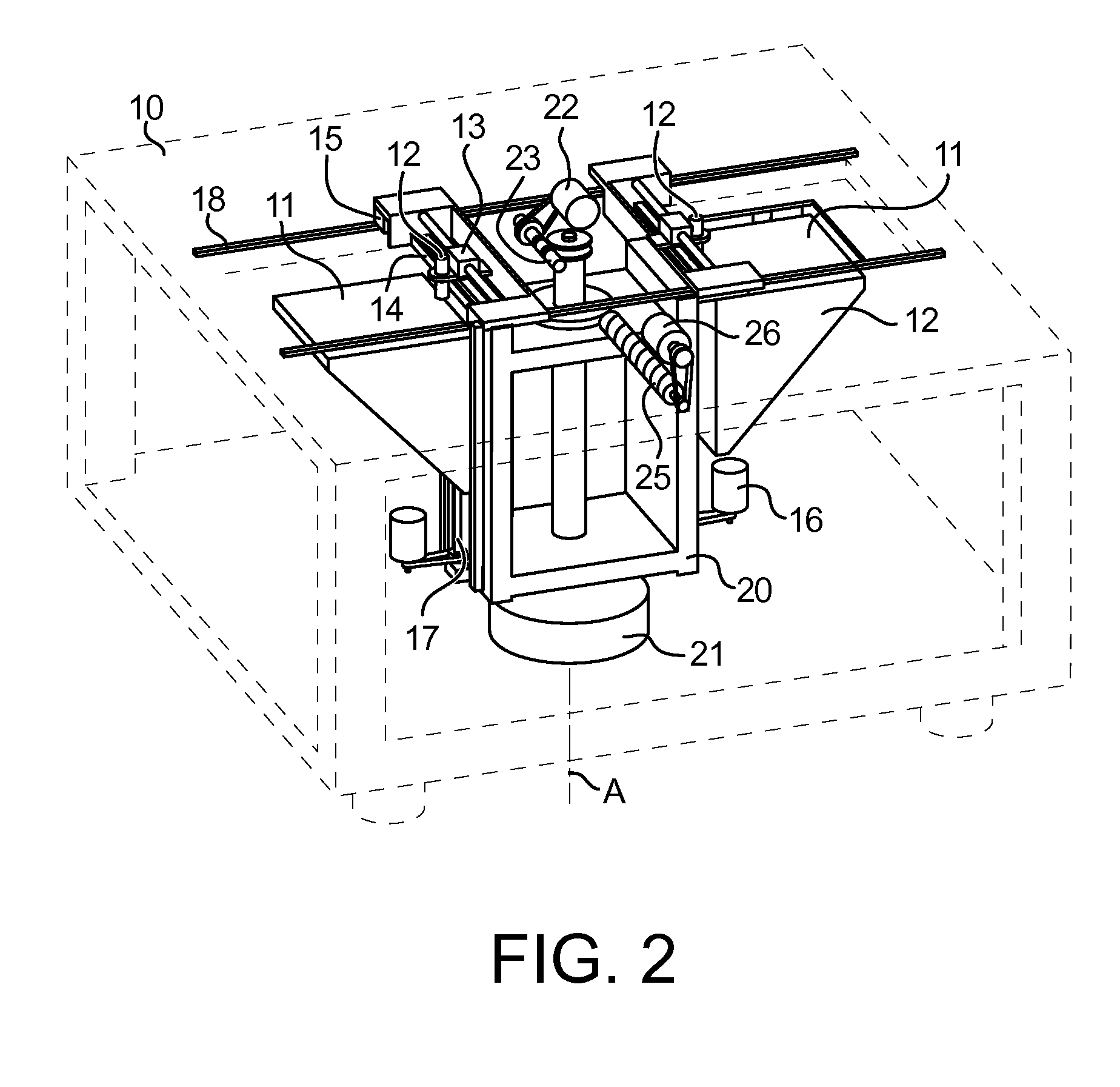
[0033]With reference to FIG. 2, a preferred embodiment of the inventive machine provides that on a frame 10 of the machine, two work platforms 11 are mounted. These platforms are pivot mounted about a main vertical axis A, so that they can rotate about this axis and take up position alternately under two work stations symbolized by the two groups of tooling shown.

[0034]More precisely, a crossbar 20 forming a carrier structure is pivot mounted about the main axis A.

[0035]An encoder 21 is located underneath the crossbar 20, so as to be able to command its rotation about the main axis A. This crossbar 20 carries two supports 12 themselves each bearing a work platform 11. The two supports 12 are mounted mobile in vertical translation, parallel to the main axis A by means of two respective guide screws 17 and each driven by a motor 16. This movement allows progressive lowering of each of the platforms 11 after the depositing of a layer, during the manufacturing process of each object.

[00...


PUM

PropertyMeasurementUnit
Forceaaaaaaaaaa
Angleaaaaaaaaaa
Angleaaaaaaaaaa

Abstract

Inventive machine allowing the simultaneous fabrication of several objects by a method of “rapid prototyping” type, by depositing a succession of layers of heat-fusible fluid.It chiefly comprises a crossbar (20) carrying two platforms (11) on each of which an object is fabricated by deposition. Two fixed work stations are arranged diametrically opposite each other so that the jet (12) of each of these fixed stations can perform a depositing operation at the same time as the other jet (12). After each deposit, the crossbar is rotated 180° to alternate the depositing operations of the two different materials.Particular application to prototyping jewellery models.

Description

FIELD OF THE INVENTION[0001]The invention pertains to the production of objects in three dimensions by depositing successive layers, and more precisely to models. It therefore also concerns the area of <<rapid prototyping >>. It applies, inter alia, to the manufacture of models requiring high construction accuracy such as models for jewellery, spectacles, electronic packaging, aeronautics.PRIOR ART AND PROBLEM RAISED[0002]In the area of jewellery, it is known to produce models in three directions using so-called “rapid prototyping” systems. One type of these systems is based on placing heat-fusible material on a work platform, mobile along a vertical axis. This type of process consists of depositing a high number of successive layers, of constant or different thickness, whose successive surface areas correspond to the gradual forming, along a vertical axis, of the model to be produced. It is therefore necessary to define a large number of sections of the object to be pro...

Claims


Application Information

Patent Timeline
IPC IPC(8): B29C35/04B29C31/10B29C67/00
CPCB29C67/0055B33Y30/00B33Y10/00B29C64/118B29C64/106B29C64/182
Inventor MARSAC, NICOLAS
Owner MARSAC NICOLAS
Learn More