
Finger-type pulse detection wireless transmission structure

Inactive Publication Date: 2009-01-15
HUNG CHIN YEH
View PDF10 Cites 17 Cited by
  • Summary
  • Abstract
  • Description
  • Claims
  • Application Information

AI Technical Summary

Benefits of technology

[0011]It is a main object of the invention to provide a finger-type pulse detection wireless transmission structure having a pulse detector that is minimized in size for binding onto a finger. Thus, the structure in accordance with the invention is light, convenient, and burdenfree. Meanwhile, it is also suitable for the female users to use without affecting their movement.
[0012]It is another object of the invention to provide a finger-type pulse detection wireless transmission structure having a pulse detector in close contact to the finger's skin without worrying about any undesired slip or displacement. Thus, an accurate measurement of the tiny change of the reflected infrared caused by the blood flowing action within the blood vessel each time due to the pulsation is ensured. Accordingly, the accuracy in measurement can be improved.
[0013]It is a further object of the invention to provide a finger-type pulse detection wireless transmission structure that permits an automatic power on when putting on the finger and an automatic power off when removed. In this way, the consumption of the electric power can be reduced for prolonging its service life.

Problems solved by technology

To take exercise properly and advantageously, the heart rate must increase to 60% of the maximum rate; however, if the heart rate increases to the maximum rate during exercise, it will do harm to the exerciser.
However, it is found that the patent is poor with the following conditions when being applied.
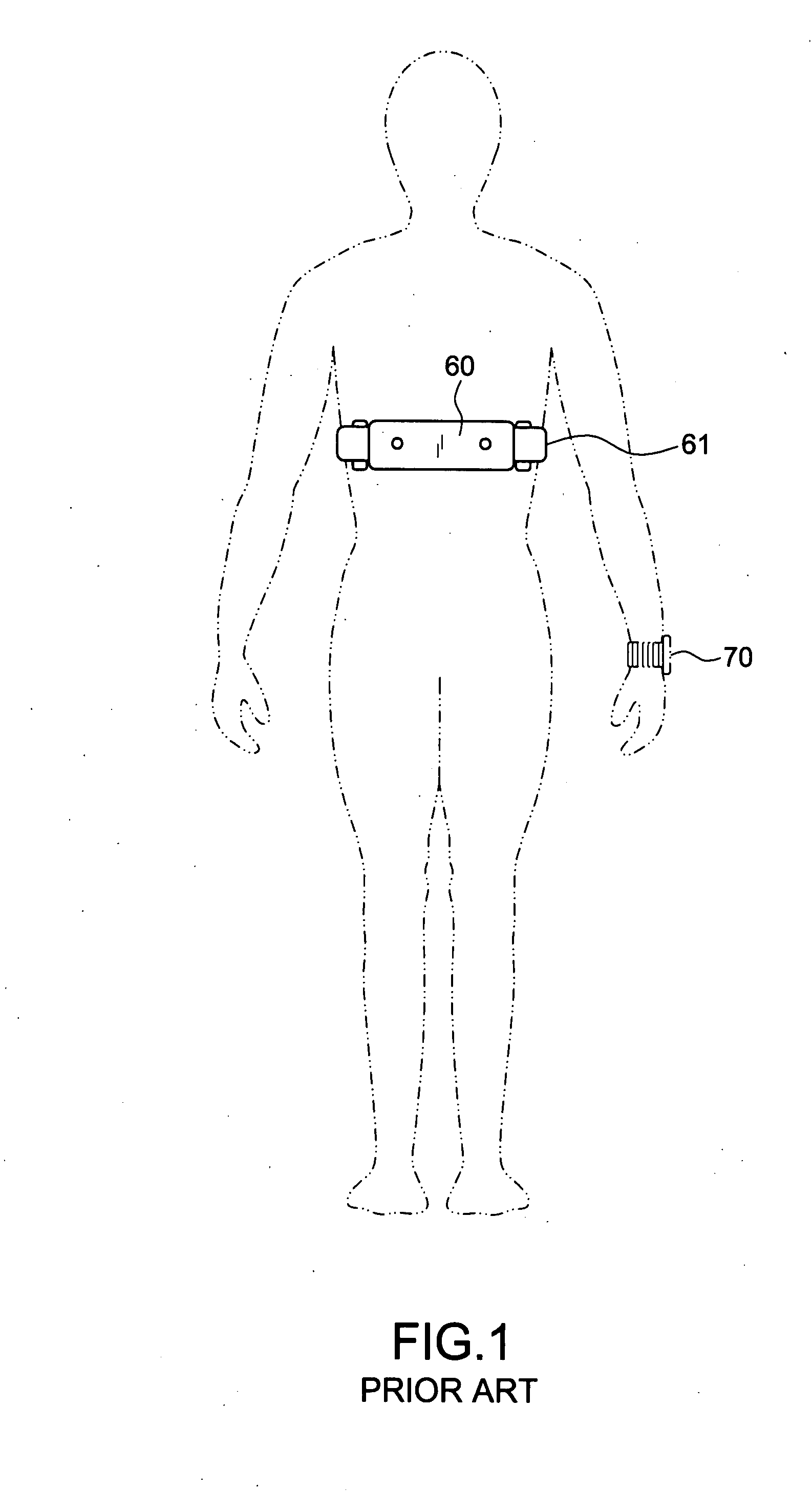
1. In general, the heart rate monitoring unit 60 is tightly bound with the belt 61 on the chest to keep close to; however, the lung capacity increases during exercise and thus the belt bound up on the chest causes a user to be uncomfortable and breathe hard.
3. To accurately measure the heart rate, the heart rate monitoring unit 70 cannot be bound outside the clothes but inside the clothes and close to the chest, so the belt 71 is placed certainly after the clothes is taken off, which might be somewhat inconvenient to males but may be implemented none the less; however, it is very inconvenient to females to bind up the belt 71 in a public place; thus, the conventional belt is not suitable for the female users.
However, this conventional unit is not suitable for use during the exercise sessions since the large movement will change the detected signals.
This is very impractical.

Method used


Image

  • Finger-type pulse detection wireless transmission structure
  • Finger-type pulse detection wireless transmission structure
  • Finger-type pulse detection wireless transmission structure

Examples


Embodiment Construction

[0021]Now, the present invention will be described more specifically with reference to the following embodiments. It is to be noted that the following descriptions of preferred embodiments of the invention are presented herein for purpose of illustration and description only; it is not intended to be exhaustive or to be limited to the precise form disclosed.

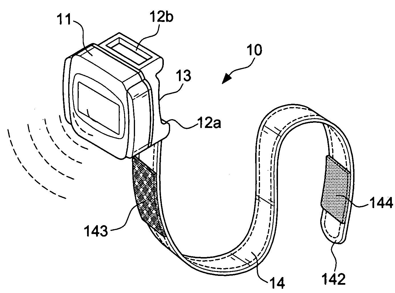
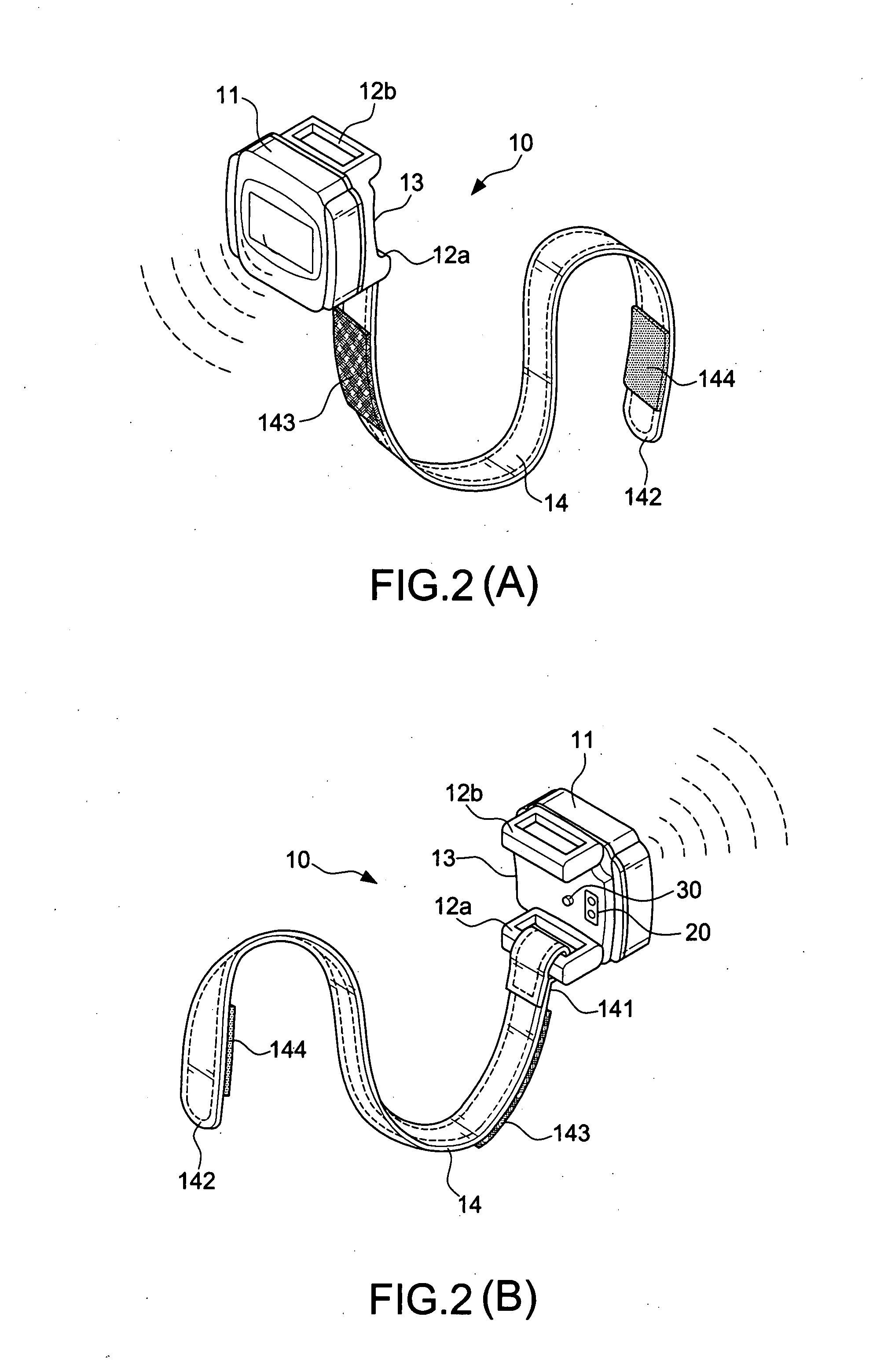
[0022]First, with reference to FIGS. 2A, 2B, 3, and 4, the invention mainly includes a finger-type pulse detector 10 and a display storage unit 50 separate therefrom. The finger-type pulse detector 10 includes a housing 11, a sensitive switch 30, a finger fixing band 14, a noise-canceling circuit 32, a filtering shaping amplifying circuit 33, and a radio frequency module 40.

[0023]The housing 11 is made according to the finger's contour. A first lug 12a and a second lug 12b are formed at both sides of the housing 11. An infrared pulse sensor 20 is disposed at the bottom of the housing 11 for detecting the change of a slight amount...


PUM


Abstract

A finger-type pulse detection wireless transmission structure, comprising: a) a housing made according to a finger's contour, a first lug and a second lug being formed at both sides of the housing, an infrared pulse sensor being disposed at the bottom of the housing for detecting the change of a slight amount of blood within the blood vessel of a user's finger that is caused by the pulsation such that the heartbeat pulse signal of the user is available; b) a sensitive switch disposed at the bottom of the housing for turning power on and off the infrared pulse sensor; c) a finger fixing band having a first end connected to the first lug and a second end passing through the second lug, the finger fixing band being stuck in an reverse direction to the external side such that the housing can be bound to the finger while the infrared pulse sensor and the sensitive switch are in close contact to the finger's skin; d) a noise-canceling circuit and a filtering shaping amplifying circuit installed within the housing and electrically coupled to the infrared pulse sensor; and e) a radio frequency module having a wireless signal transmission circuit and provided within the housing for transmitting the heartbeat pulse signal of the filtering shaping amplifying circuit to a display storage unit provided with a wireless signal receiving circuit such that the heartbeat pulse signal can be displayed.

Description

BACKGROUND OF THE INVENTION[0001]1. Field of the Invention[0002]The invention relates to a pulse detector, and more particularly, to a structure having a detection unit put on a finger while the heartbeat signal is wirelessly transmitted to a display storage unit for achieving an easy use and an accurate measurement of the heartbeat.[0003]2. Description of the Related Art[0004]Conventionally, people's heart rate remarkably varies before and after people take exercise. During exercise, measuring the variables is very important. To take exercise properly and advantageously, the heart rate must increase to 60% of the maximum rate; however, if the heart rate increases to the maximum rate during exercise, it will do harm to the exerciser. Thus, a user-friendly and precise heart rate measurement device is very important for taking exercise to keep fit.[0005]Next, FIG. 1 shows an electrode belt of heart rate monitor disclosed in U.S. Pat. No. 6,553,247, in which a heart rate monitoring uni...

Claims


Application Information

Patent Timeline
IPC IPC(8): A61B5/02
CPCA61B5/0002A61B5/6838A61B5/6826A61B5/02438
Inventor HUNG, CHIN-YEH
Owner HUNG CHIN YEH
Learn More