
LMS adaptive filter

Inactive Publication Date: 2005-03-03
LG ELECTRONICS INC
View PDF11 Cites 4 Cited by
  • Summary
  • Abstract
  • Description
  • Claims
  • Application Information

AI Technical Summary

Benefits of technology

[0020] An object of the present invention is to provide an LMS adaptive filter, by which signal distortion due to time interval is compensated and by which a filter size can be minimized.

Problems solved by technology

However, the related filter having many taps has difficult in implementation since a size of the filter should be increased to include many taps therein.

Method used


Image

  • LMS adaptive filter
  • LMS adaptive filter
  • LMS adaptive filter

Examples


first embodiment

[0035] First Embodiment

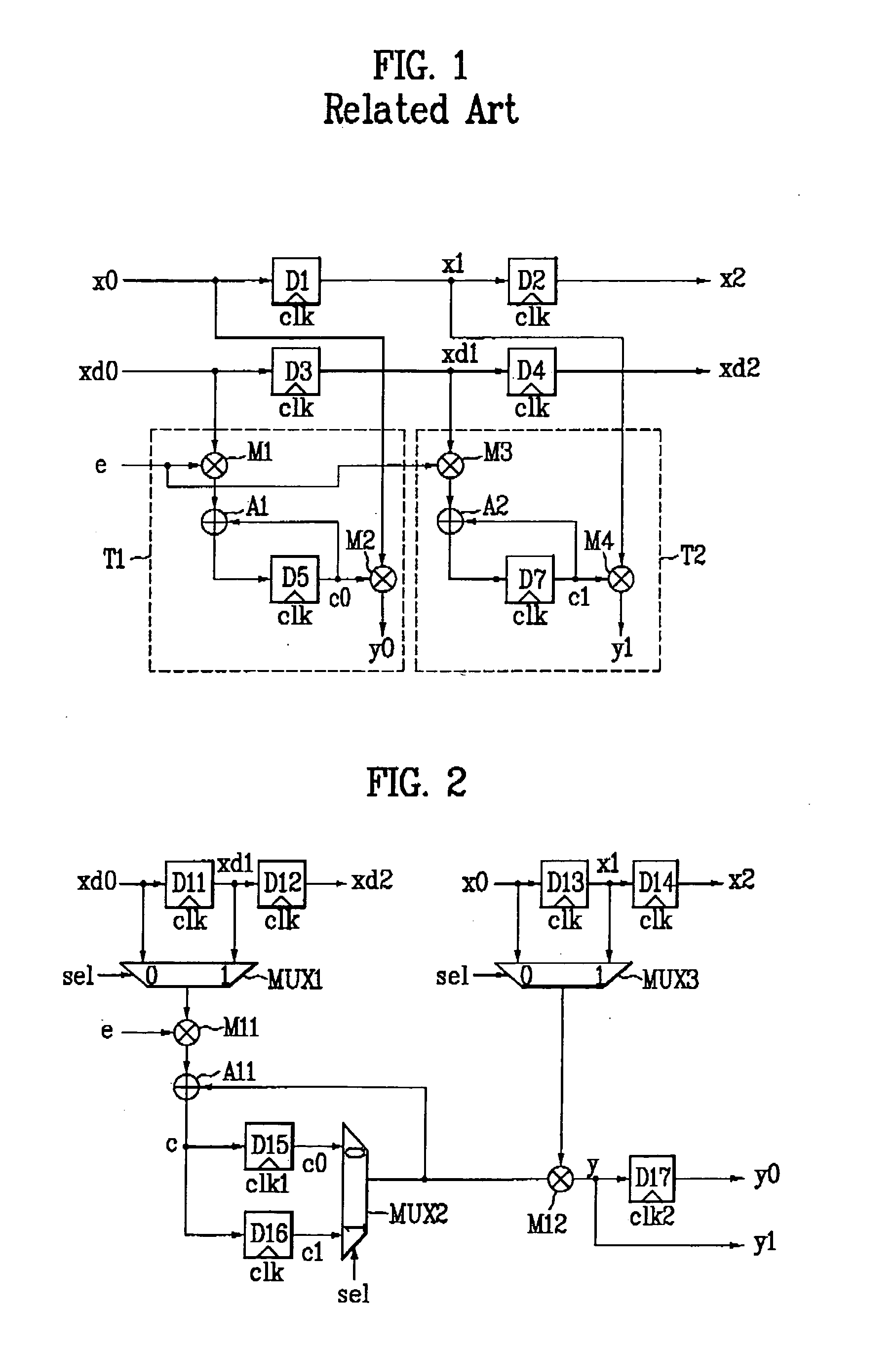
[0036]FIG. 2 is a block diagram of an LMS adaptive filter according to a first embodiment of the present invention.

[0037] Referring to FIG. 2, a first delayer D11 receives a signal xd0 delayed by a prescribed time behind an input signal x0 and outputs a signal xd1 delayed more than the delayed signal xd0. A second delayer D12 receives the delayed signal xd1 and outputs a signal xd2 delayed more than the delayed signal xd1. A third delayer D13 receives the input signal x0 and outputs a signal x1 delayed more than the input signal x0. And, a fourth delayer D14 receives the delayed signal x1 and outputs a signal x2 delayed more than the delayed signal x1. The first to fourth delayers D11 to D14 are synchronized with a reference clock signal elk to output the delayed signals xd1, xd2, x1, and x2, respectively. Each of the delayed signals xd1, xd2, x1, and x2 is delayed more than the input signal x0. Each delay time of the delayed signals xd1, xd2, x1, and x2 can ...

second embodiment

[0055] Second Embodiment

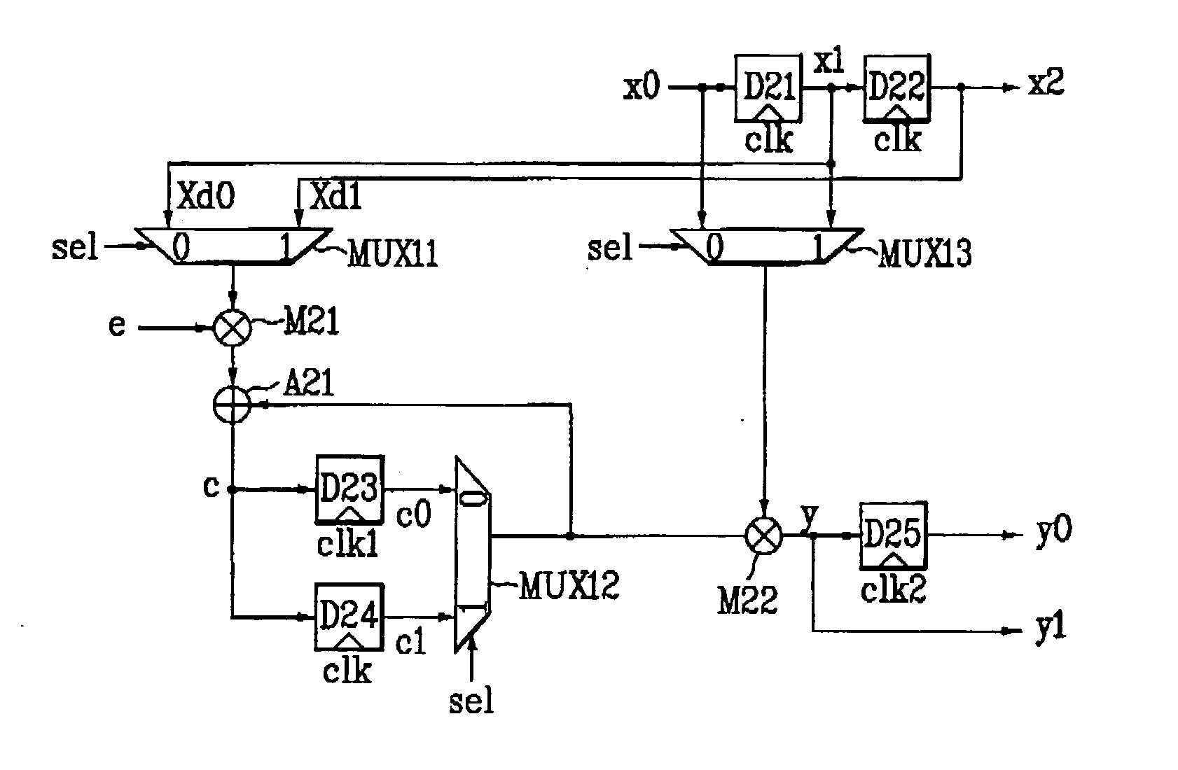
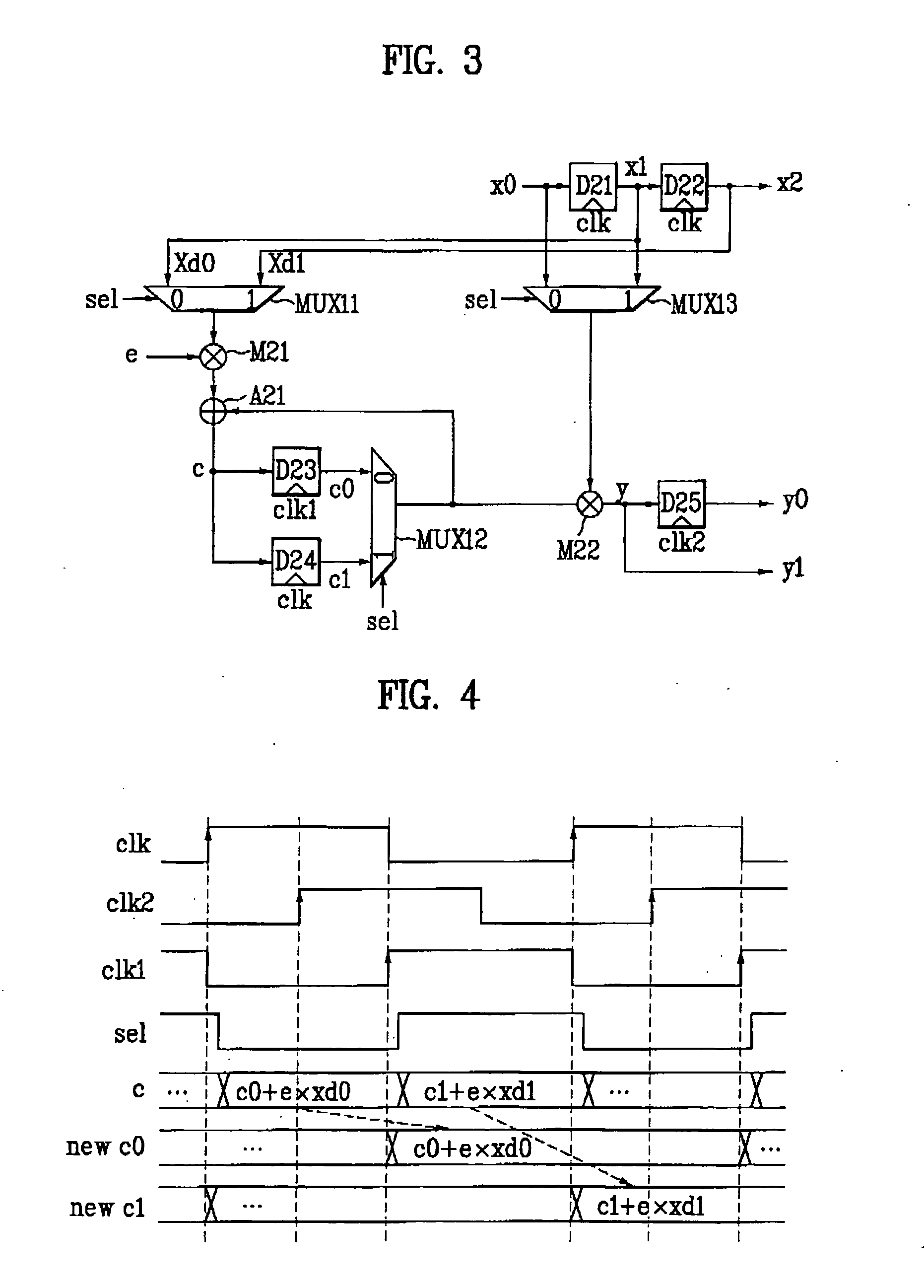
[0056]FIG. 3 is a block diagram of an LMS adaptive filter according to a second embodiment of the present invention.

[0057] Referring to FIG. 3, a first delayer D21 receives an input signal x0 and outputs a signal x1 delayed by a prescribed time behind the input signal x0. A second delayer D22 receives the delayed signal x1 and outputs a signal x2 delayed more than the delayed signal x1. The first and second delayers D11 and D12 are synchronized with a reference clock signal clk to output the delayed signals x1 and x2, respectively.

[0058] A first multiplexer MUX11 receives the two delayed signals xd0 and xd1. In this case, the delayed signals xd0 and xd1 are the signals x1 and x2 outputted from the first and second delayers D21 and D22, respectively. The first multiplexer MUX11 selectively outputs one of the delayed signals xd0 and xd1 according to a logic value or level of a selection signal sel inputted from outside.

[0059] A first multiplier M21 receives ...


PUM


Abstract

The present invention provides an LMS adaptive filter, by which signal distortion due to time interval is compensated and by which a filter size can be minimized. The present invention includes a first multiplier alternately outputting a value calculated by multiplying a first delayed signal and an error signal together and a value calculated by multiplying a second delayed signal and the error signal together, an adder adding a signal outputted from the first multiplier to a previous coefficient, a first delayer receiving a signal outputted from the adder and outputting a first new coefficient by synchronization with a first clock, a second delayer receiving the signal outputted from the adder and outputting a second new coefficient by synchronization with a reference clock, a second multiplier alternately outputting a value calculated by multiplying the first new coefficient and the input signal and a value calculated by multiplying the second new coefficient and a third delayed signal, and a third delayer outputting a signal outputted from the second multiplier by synchronization with a second clock.

Description

[0001] This application claims the benefit of the Korean Application No. P2003-60219 filed on Aug. 29, 2003, which is hereby incorporated by reference. BACKGROUND OF THE INVENTION [0002] 1. Field of the Invention [0003] The present invention relates to an LMS (least mean square) adaptive filter applicable to an equalizer, noise remover, and the like of a digital TV. [0004] 2. Discussion of the Related Art [0005] Generally, a least mean square (hereinafter abbreviated LMS) adaptive filter is a filter keeping updating a coefficient using TMS adaptive algorithm. The LMS adaptive filter is operative in compensating a signal distortion caused by channels or a system itself. [0006]FIG. 1 is a structural diagram of an LMS adaptive filter according to a related art. [0007] Referring to FIG. 1, a first delayer D1 receives an input signal x0 and outputs a delayed signal x1. A second delayer D2 receives the delayed signal x1 and outputs a delayed signal x2. A third delayer D3 receives a delaye...

Claims


Application Information

Patent Timeline
IPC IPC(8): G06F17/10H03H21/00H04L25/03
CPCH03H21/0012H04L2025/03617H04L2025/03382H03H21/00
Inventor KIM, WOO CHAN
Owner LG ELECTRONICS INC
Learn More