Utrasound probe and ultrasound elasticity imaging apparatus

a technology of ultrasound elasticity and ultrasound probe, which is applied in the direction of ultrasonic/sonic/infrasonic image/data processing, applications, and catheters. it can solve the problems of large tissue distortion, small tissue distortion, and large tissue distortion, and achieve excellent usability for the operator. elasticity imaging

Active Publication Date: 2009-01-15
FUJIFILM HEALTHCARE CORP
View PDF12 Cites 12 Cited by
  • Summary
  • Abstract
  • Description
  • Claims
  • Application Information

AI Technical Summary

Benefits of technology

[0045]As described above, whether a pressing operation is proper or not is immediately displayed on the display device, and thus the operator can obtain a proper elastic image by adjusting a pressure operation with pressing device (e.g., probe) depending upon whether a displayed pressing state is proper or not. Further, whether a pressing operation is proper or not is decided by analyzing displacement data, and thus it is possible to decide the suitability of a pressing operation in consideration of variations among subjects. Consequently, it is possible to achieve elasticity imaging with excellent usability for the operator.

Problems solved by technology

In a time phase when a distortion within a proper range is not applied, extracted elastic image data is disturbed.
When obtaining ultrasound received signal frame data of a pair of frames at regular time intervals, a high pressing speed at a certain time causes large distortion of a tissue at that time, and a low pressing speed at a certain time causes small distortion of a tissue at that time.
Thus, it is difficult to keep pressing within a pressing speed range suitable for high image quality all the time in a series of pressing processes.
Further, a pressing speed is not constant at respective times, so that a plurality of outputted elastic image data becomes temporally discontinuous and elastic images become discontinuous between frames.
Further, it is not possible to avoid a movement of hands in the pressing process.
In this manner, due to an improper pressing direction or an excessive speed, ROI set by the imaging apparatus may have an error (correlation operation error) region, in which a correct displacement cannot be calculated.
In a deep region where transmitted ultrasound waves can not reach due to attenuation and in a region with few ultrasound reflectors (a cyst and a lesion having a liquid therein), ROI set by the imaging apparatus may have an error (correlation operation error) region, in which a correct displacement cannot be calculated, because no received signal reflecting a property of the tissue of interest with sufficient intensity cannot be obtained.
In these cases, a distortion image is not correctly displayed in the error region.
Furthermore, a region having a displacement close to 0 may be entirely distributed in ROI set by the imaging apparatus due to a pressing speed of 0 or an insufficient pressing speed.
Such pressing speeds occur when a pressure is not applied to a tissue of interest at time intervals for obtaining a pair of ultrasound received signal frame data and a pressing speed on a tissue of interest is too low.
Therefore, even though image information on a region calculated under improper conditions is not worth displaying, the image information cannot be discriminated from information worth displaying.
As a result, an elastic image of one frame is constructed such that a region worth displaying and a region not worth displaying are mixed, reducing the reliability of an elastic image.
Hence, it is not always possible to obtain a proper elastic image.
Without a certain distortion difference between adjacent two frames, a proper elastic image cannot be generated.
A pressing state is considerably changed by the feeling of the operator, and thus it is not always possible to obtain a proper elastic image.
Similarly, because of variations among subjects, even when an operation is performed in a uniform pressing state, a proper elastic image cannot be always obtained.
Further, a pressing direction and the way to press may cause lateral displacement on a living tissue.
Also in this pressing operation, an elastic image may include disturbance (noise) caused by lateral displacement and a proper elastic image may not be obtained.

Method used


Image

  • Utrasound probe and ultrasound elasticity imaging apparatus
  • Utrasound probe and ultrasound elasticity imaging apparatus
  • Utrasound probe and ultrasound elasticity imaging apparatus

Examples


Embodiment Construction

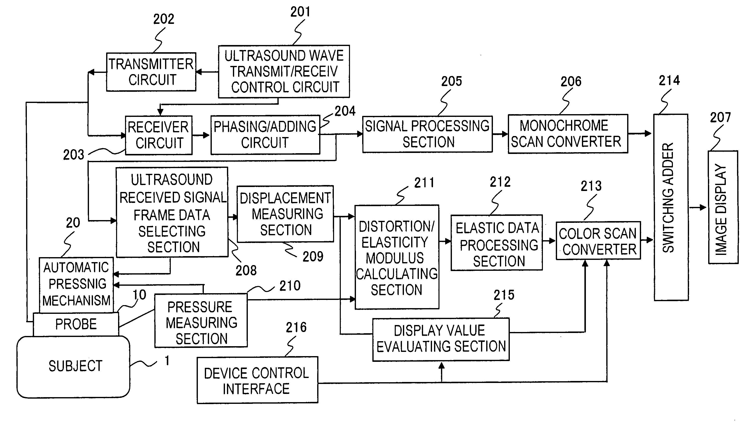
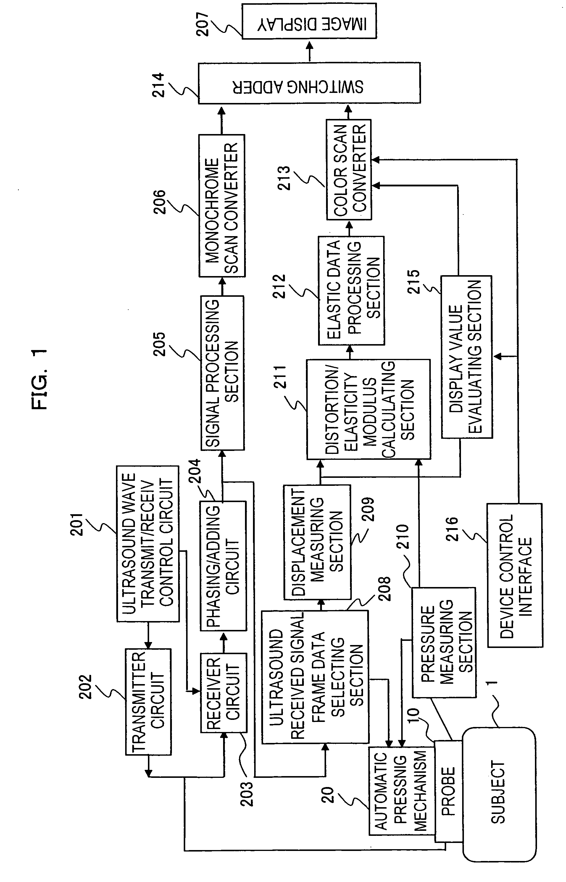
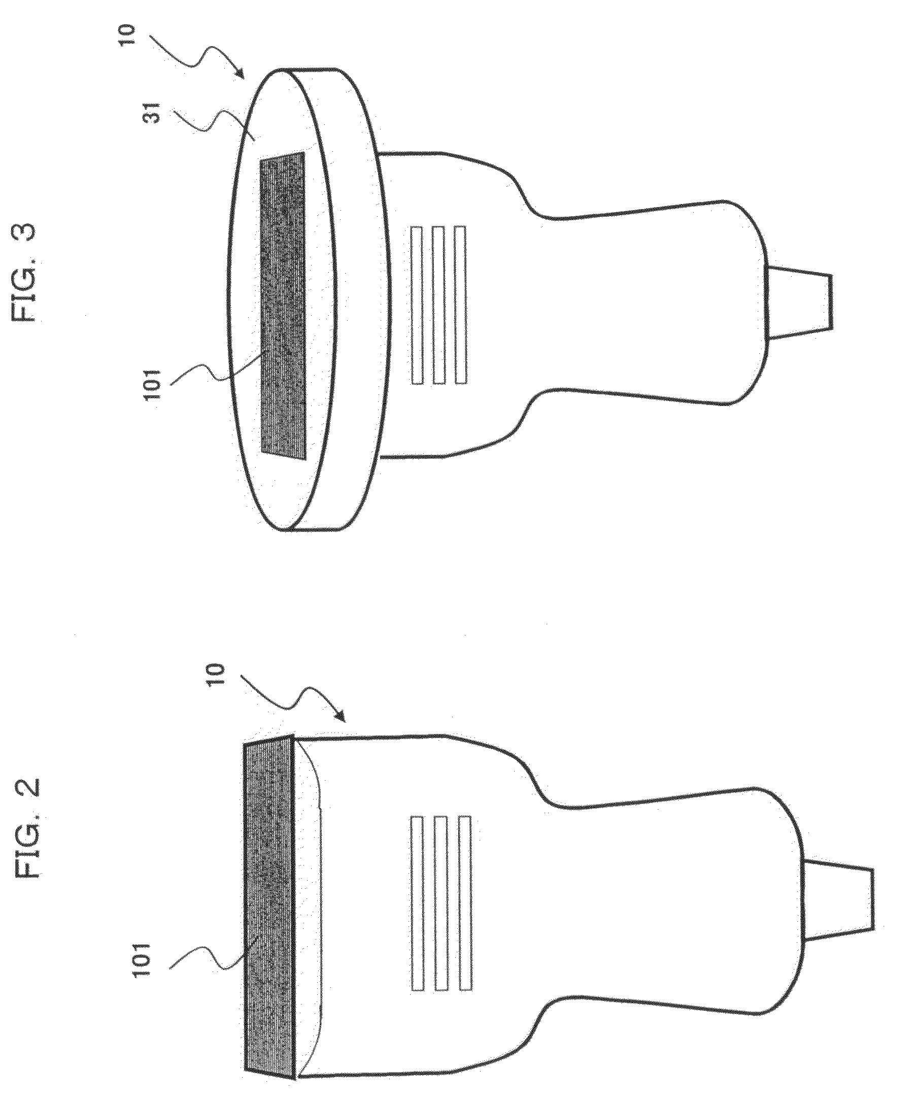
[0087]The following will specifically describe examples of the present invention in accordance with the accompanying drawings. FIG. 1 is a block diagram showing an embodiment of an ultrasound imaging apparatus according to the present invention. The ultrasound imaging apparatus obtains a tomographic image of a target part in a subject 1 by using ultrasound waves and displays an elastic image indicating the hardness of a living tissue. As shown in FIG. 1, the ultrasound imaging apparatus comprises an ultrasound probe 10 having an automatic pressing mechanism 20, an ultrasound wave transmit / receive control circuit 201, a transmitter circuit 202, a receiver circuit 203, a phasing / adding circuit 204, a signal processing section 205, a monochrome scan converter 206, an image display 207, an ultrasound received signal frame data selecting section 208, a displacement measuring section 209, a pressure measuring section 210, a distortion / elasticity modulus calculating section 211, an elastic...


PUM


Abstract

An ultrasound diagnostic apparatus includes an ultrasound probe which transmits / receives an ultrasound wave with respect to a subject to be diagnosed, an ultrasound wave transmit section which transmits an ultrasound wave for driving the ultrasound probe, a pressing section which applies an external pressure to the subject, a displacement measuring section which obtains two tomographic image data different in time series from a reflected echo signal received from the ultrasound probe and measures a displacement of each part in the subject based on the two tomographic image data, an image generating section which generates an elastic image from elasticity information based on the displacement of each part measured by the displacement measuring section, and a display section which displays the generated elastic image. Further, a pressing decision section decides whether or not the pressing operation by the pressing section is proper.

Description

CROSS REFERENCE TO RELATED APPLICATION[0001]This application is a continuation application of U.S. application Ser. No. 11 / 558,642, filed Nov. 30, 2005, the contents of which are incorporated herein by reference.TECHNICAL FIELD[0002]The present invention relates to an ultrasound imaging apparatus and an ultrasound probe of the apparatus, by which a tomographic image of a target part in a subject is obtained by using ultrasound waves, and particularly relates to an ultrasound elasticity imaging apparatus and an ultrasound probe of the apparatus, by which a distortion and a modulus of elasticity are calculated for each point in a subject based on ultrasound received signal data of consecutive time-series frames to display an elastic image indicating the hardness of a tissue.BACKGROUND ART[0003]For ultrasound imaging apparatuses, the following methods are available: one method is to apply an external force to a subject via an ultrasound wave transmit / receive surface of an ultrasound pr...

Claims


Application Information

Patent Timeline
Patent Type & Authority Applications(United States)
IPC IPC(8): A61B8/00A61B8/08
CPCA61B5/0048A61B5/6843A61B8/08A61B8/445A61B8/463A61B8/485A61B8/12
Inventor OSAKA, TAKASHIMATSUMURA, TAKESHIHAYASHI, TETSUYAOSHIKI, MITSUHIROYUASA, OKINORIMURAYAMA, NAOYUKISHIINA, TSUYOSHITAMANO, SATOSHIMITAKE, TSUYOSHI
Owner FUJIFILM HEALTHCARE CORP
Why Eureka
Try Eureka