Eureka AIR delivers breakthrough ideas for toughest innovation challenges, trusted by R&D personnel around the world.

Adjustment of target ventilation in a servoventilator

a technology of servoventilator and target ventilation, which is applied in the direction of valves, respirators, mechanical devices, etc., can solve the problems of affecting the operation of the upper airway, and particularly in patients newly introduced to servoventilation

Active Publication Date: 2009-01-15
RESMED LTD
View PDF13 Cites 37 Cited by
  • Summary
  • Abstract
  • Description
  • Claims
  • Application Information

AI Technical Summary

Benefits of technology

[0008]Various constraints may be added to modify the rate of increase of target ventilation. For example, if the pressure support level is too high, possibly indicating glottic or upper airway closure, the rate of increase of target ventilation may be lowered or even set to zero temporarily, so it takes longer to reach the final target ventilation, or in some cases the final target ventilation may never be achieved.

Problems solved by technology

In the field of noninvasive ventilation, for example as described in U.S. Pat. No. 6,532,957, a problem arises particularly in patients newly introduced to servoventilation.
Yet if the clinician sets the target ventilation of the servoventilator to 4 / 3 of the patient's current ventilation, such a large increase in ventilation, if it occurs immediately, is likely to abolish all respiratory drive and much of the upper airway drive (leading to problems with upper airway obstruction).
It may cause glottic closure, preventing the ventilation from increasing to the target level, despite the ventilator delivering the maximum level of pressure support for which it is programmed, which may lead to arousal from sleep.
If the arterial pH is relatively normal at the beginning of therapy, indicating a metabolic compensation for a relatively chronic respiratory acidosis, a sudden large increase in ventilation would result in a marked alkalosis, with undesirable electrolyte shifts, including hypokalaemia, with the potential for inducing cardiac arrhythmias.
This might be achieved by frequent manual changes of the target ventilation, but this would be inconvenient, since the patient is likely to be at home at this stage.

Method used


Image

  • Adjustment of target ventilation in a servoventilator
  • Adjustment of target ventilation in a servoventilator
  • Adjustment of target ventilation in a servoventilator

Examples


Embodiment Construction

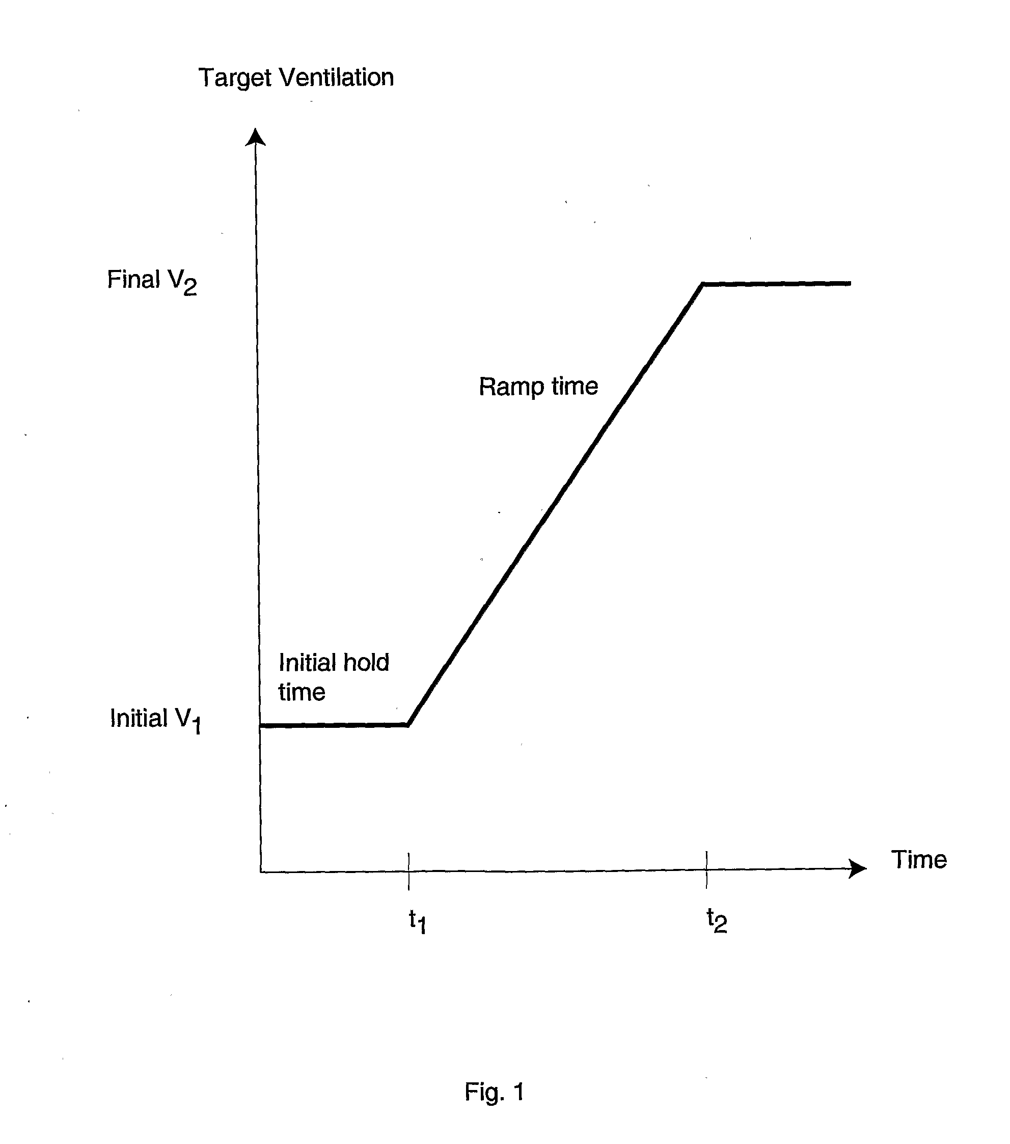
[0009]FIG. 1 illustrates an embodiment of my invention. The x-axis shows time, the y-axis shows ventilator target ventilation.

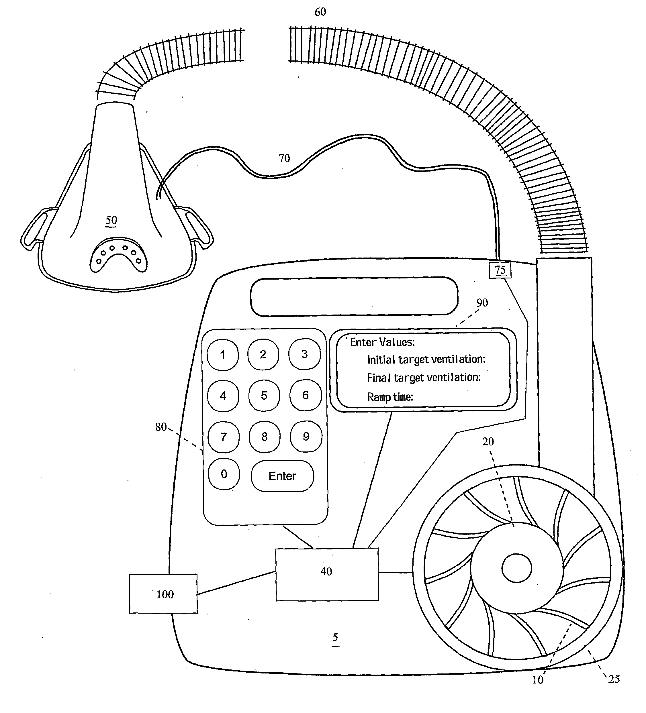
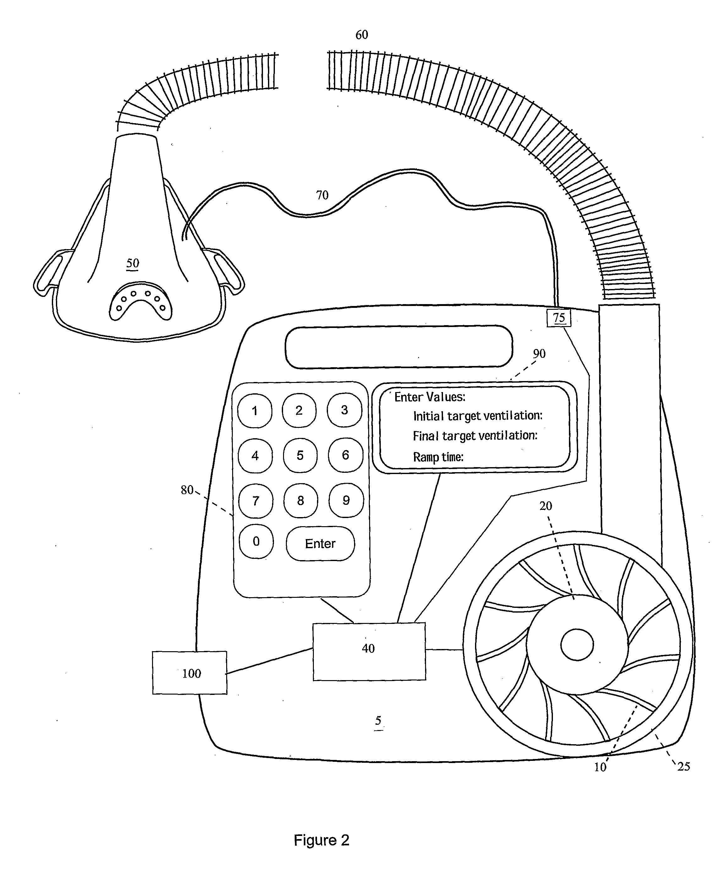
[0010]FIG. 2 illustrates servo-ventilator apparatus 5 suitable to perform the invention. An electric motor 20 has an impeller 10 and is under the control of a controller circuit 40. In use the motor and impeller is housed in a volute 25, which in use allows a flow of pressurized air to pass along the air delivery conduit 60 to a suitable patient interface 50. The patient interface 50 may be a nasal mask, or nose and mouth mask, a full-face mask or some other suitable device. A pressure sense tube 70 between the patient interface 50 and a pressure sensor 75 allows the controller 40 to sense pressure in the patient interface 50. The controller 40 can also determine the flow rate and of air along the air delivery conduit 60 via a flow sensor (not shown). The apparatus includes a display 90 and keyboard 80 which allow someone, for example a clinician, to set appr...


PUM


Abstract

A servoventilator control slowly changes the target ventilation over a period of time, according to a preprogrammed schedule adapted to be set by the physician. Preferably, the target ventilation stays constant at an initial target ventilation for an initial hold time, and then increases at a constant rate until it reaches a final target ventilation, whereupon it stays constant thereafter. If the pressure support level is too high, possibly indicating glottic or upper airway closure, the rate of increase of target ventilation may be lowered or the final target ventilation not reached.

Description

[0001]This application claims the benefit of the filing of Australian Provisional application AU 2004 / 905022 filed Sep. 3, 2004.FIELD OF THE INVENTION[0002]The present invention relates to the field of ventilatory assistance, and in particular, to methods and apparatus for determining suitable ventilator settings in patients with alveolar hypoventilation during sleep, and for delivery of those settings.BACKGROUND OF THE INVENTION[0003]In the field of noninvasive ventilation, for example as described in U.S. Pat. No. 6,532,957, a problem arises particularly in patients newly introduced to servoventilation. The patient's arterial C02 partial pressure (PCO2) may be well above the value preferred by the clinician; for example, the PCO2 may be 60 mm Hg, and the clinician would prefer to stabilize it at 45 mm Hg. This would require the patient's alveolar ventilation to be increased by a factor of approximately 60 / 45=4 / 3. Yet if the clinician sets the target ventilation of the servoventila...

Claims


Application Information

Patent Timeline
IPC IPC(8): A61M16/00
CPCA61M16/00A61M16/0066A61M2205/502A61M2016/0027A61M2016/0039A61M2016/0021A61M16/022A61M16/0069A61M16/0003A61M2016/003A61M2205/3334
Inventor BASSIN, DAVID JOHN
Owner RESMED LTD
Why Eureka
Eureka Blog
Learn More