
Rigid-type electronic videoendoscope

a videoendoscope and electronic technology, applied in the field of videoendoscopes, can solve the problems of complex structure, inability to directly mount on the endoscope, and various diseases of people, and achieve the effect of easy examination of the affected part of the patien

Inactive Publication Date: 2009-01-08
WANG SOO GEUN +4
View PDF8 Cites 5 Cited by
  • Summary
  • Abstract
  • Description
  • Claims
  • Application Information

AI Technical Summary

Benefits of technology

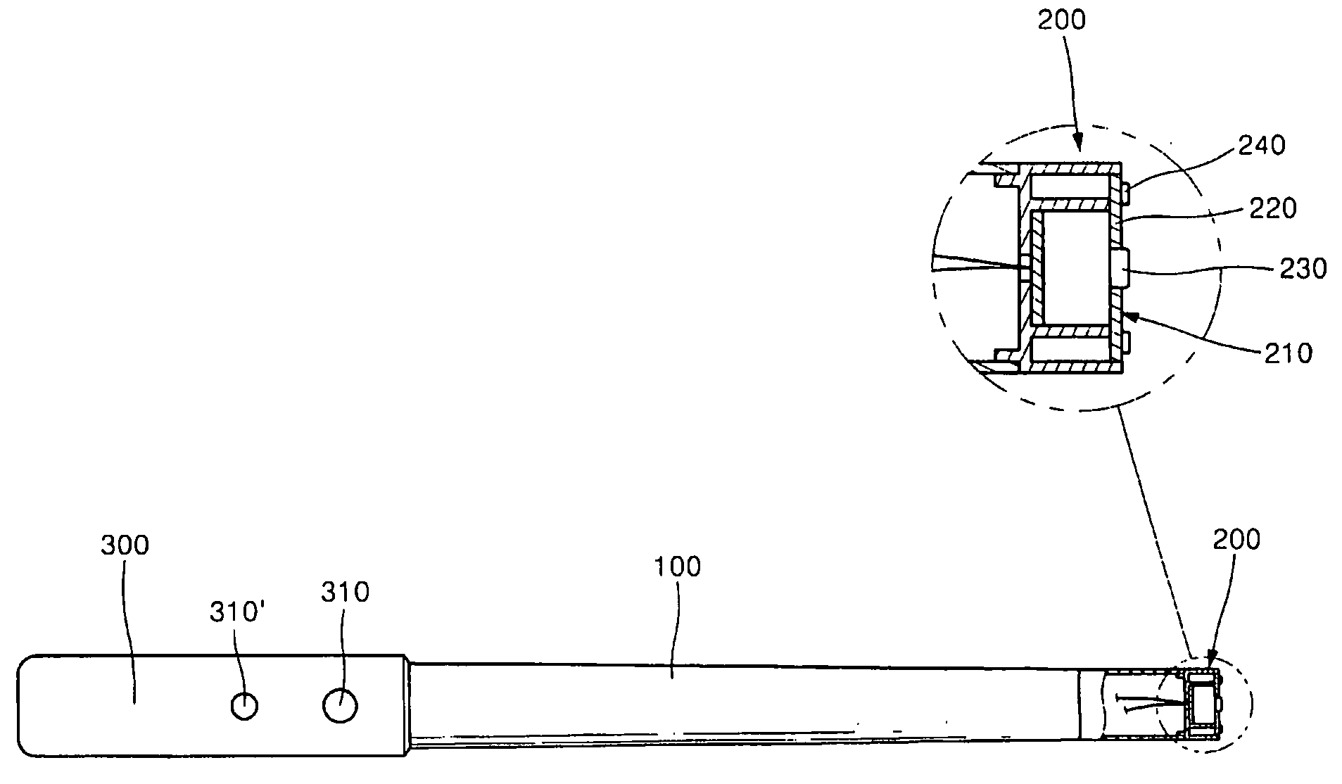
[0006]Accordingly, the present invention has been made in view of the above problems occurring in the prior art, and it is an object of the present invention to provide a rigid-type electronic videoendoscope, which can allow a doctor to easily examine a patient's affected part using an image capturing part mounted on an end portion of a support tube, which can easily turn on and off LEDs directly mounted thereon as a light source for emitting light for allowing a CCD or CMOS image sensor to capture an image of the patient's affected part, the LEDs being similar to a newly developed white light and generating a little heat since it is small in electric power consumption, and which is economical since it does not use an optical fiber which is expensive and needs optical inducement.

Problems solved by technology

Furthermore, in spite of such concerns, people suffer from various diseases.
However, in such conventional endoscope, since the light source generates heat severely, it cannot be directly mounted on the endoscope, and so is mounted separately.
So, the conventional endoscope is complicated in structure, and expensive in manufacturing cost, and causes an economic loss since it needs an expensive CCD camera system for capturing an image of the patient's affected part.

Method used


Image

  • Rigid-type electronic videoendoscope
  • Rigid-type electronic videoendoscope
  • Rigid-type electronic videoendoscope

Examples


Embodiment Construction

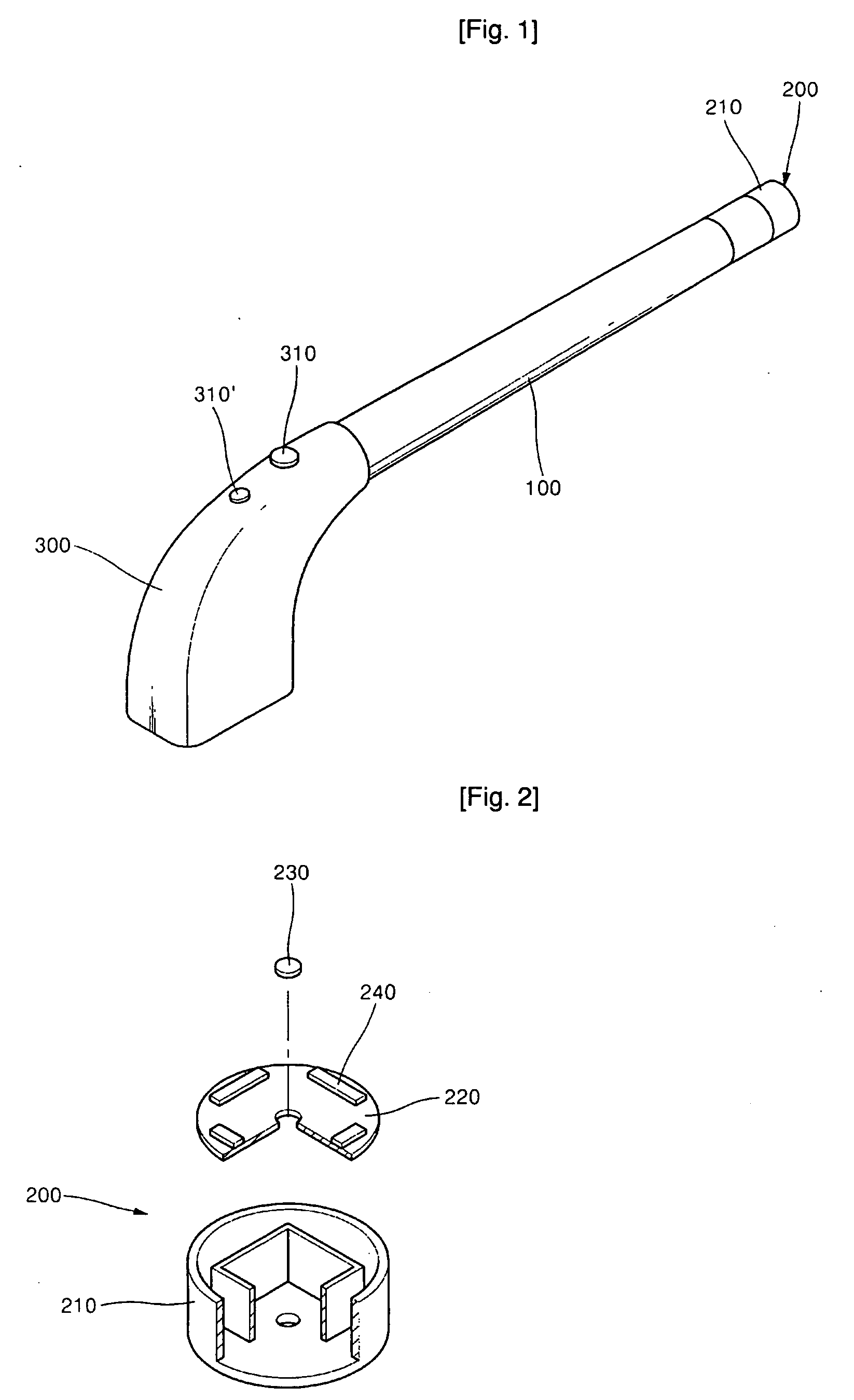
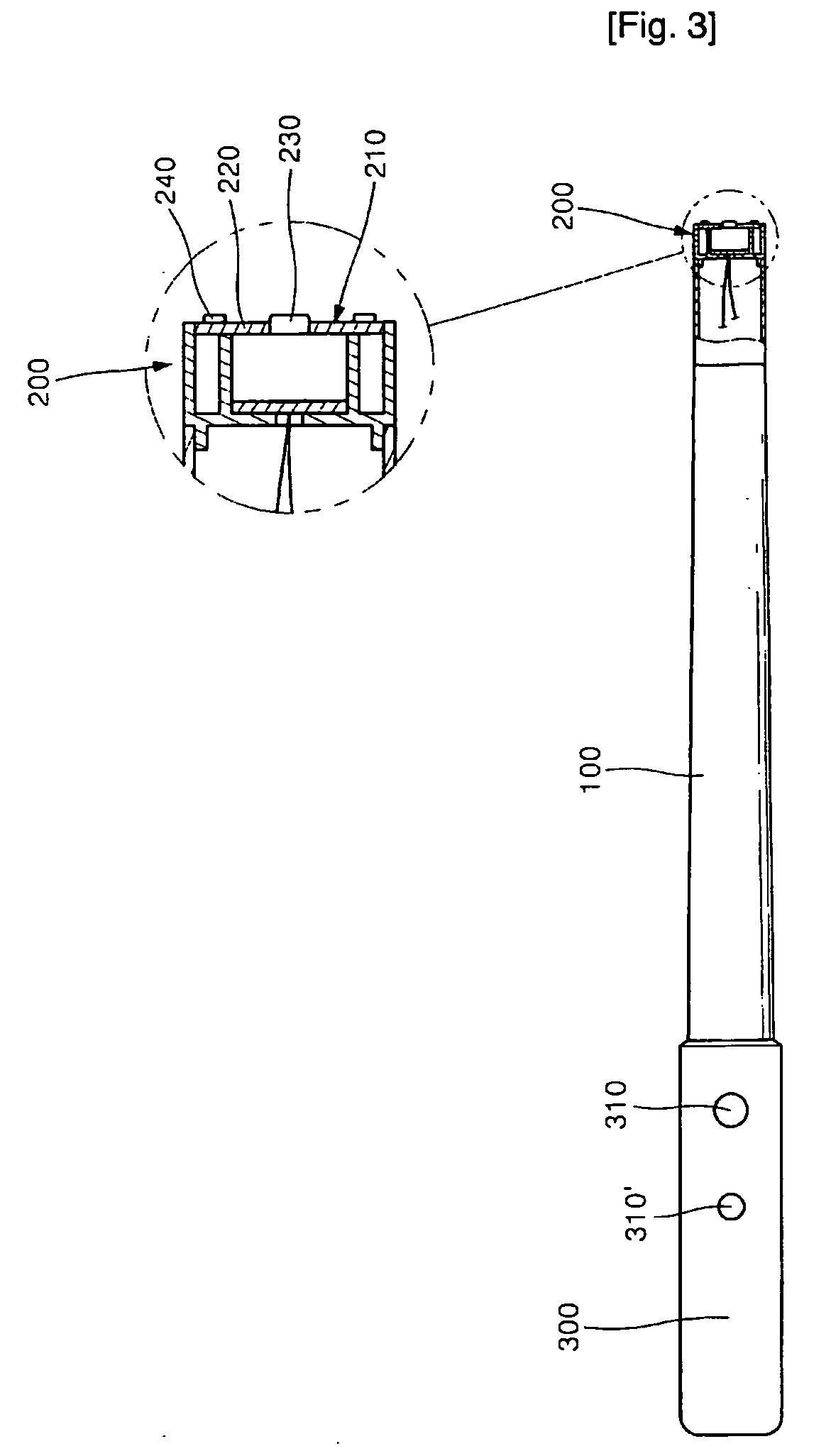
[0011]Reference will now be made in detail to the preferred embodiments of the present invention, examples of which are illustrated in the accompanying drawings. FIG. 1 is a perspective view of an electronic videoendoscope according to the present invention, FIG. 2 is an exploded perspective view of an image capturing part of the electronic videoendoscope, and FIG. 3 is a sectional view of the electronic videoendoscope.

[0012]The electronic videoendoscope according to the present invention includes a support tube 100, a shielding plate 220 and a grip 300.

[0013]The support tube 100 is inserted into the interior of a patient's body cavity for the visual examination of the lesion of the body cavity.

[0014]The image capturing part 200 comprises a housing 210, a shielding plate 220, a CCD or CMOS image sensor 230 and LEDs (Light Emitting Diode) 240. The housing 210 is mounted on an end of the support tube 100, and the housing 210 has a guide rib 211 protruding from the outer periphery of t...


PUM


Abstract

Disclosed herein is a rigid-type videoendoscope, which can allow a doctor to easily examine a patient's affected part using an image capturing part mounted on an end portion of a support tube, which can easily turn on and off LEDs for emitting light for allowing a CCD or CMOS image sensor to capture an image of the patient's affected part, and which can reduce electric power consumption, thereby improving economical efficiency.

Description

TECHNICAL FIELD[0001]The present invention relates to a rigid-type electronic videoendoscope, which can allow a doctor to easily and selectively turn on and off an image capturing part mounted on a support tube inserted into the interior of a patient's body cavity and having LEDs for the visual examination of the lesion of the body cavity.BACKGROUND ART[0002]Recently, due to the remarkable economic growth and rapid scientific development, the life quality of the moderns has been improved, and healthy life is the best target in life. Furthermore, people are highly concerned about health since they meet lots of information about health and diseases every day through mass media such as newspaper and broadcasting.[0003]The reason is that the moderns are concerned about health since they recognize that health is threatened by mental stress increased due to rapidly scientific change and development and considerable increase of economic activities, by lack of exercise and adaptation to ina...

Claims


Application Information

Patent Timeline
Patent Type & Authority Applications(United States)
IPC IPC(8): A61B1/06
CPCA61B1/0607A61B1/05A61B1/06
Inventor WANG, SOO GEUNJEON, GYE ROKRO, JUNG HOONOK, JEONG HWANWANG, YONG JIN
Owner WANG SOO GEUN
Learn More