
Method and Apparatus for Measurement Report for the Decision of Transmission Mode Transition

Active Publication Date: 2009-01-08
SAMSUNG ELECTRONICS CO LTD +1
View PDF14 Cites 25 Cited by
  • Summary
  • Abstract
  • Description
  • Claims
  • Application Information

AI Technical Summary

Benefits of technology

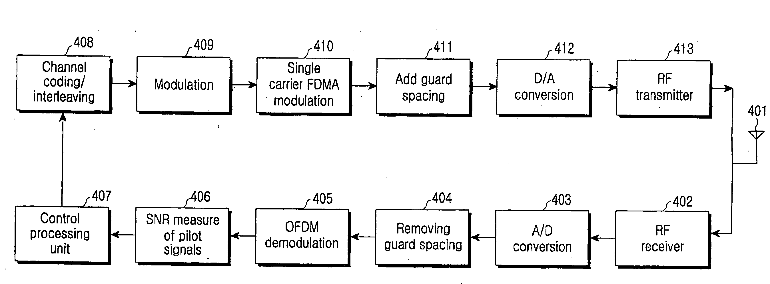
[0023]Therefore, an object of present invention is to provide a method and apparatus for creating a measurement report for making a transmission mode transition decision, by which a BS could determine whether a channel of a UE has a large frequency selectivity gain based on a measurement report and indicate the mode suitable for the UE based on the determined result.
[0025]In present invention, after the UE has reported the measurement report to the BS, the BS may choose a more suitable data transmission mode for the UE based on this measurement report to provide more effective data transmission. This measurement report may make the UE choose distributed data transmission in flat fading channel with good channel condition, thus reducing uplink CQI report signaling load on the premises of not impacting transmission gain.

Problems solved by technology

However, for some channels which change very fast, channel conditions predicted at some time can't reflect that of the next time, therefore localized transmission is hard to implement.
However, for data transmission in a flat fading channel condition, localized data transmission can't acquire much selective frequency gain compared to distributed data transmission, because SNRs of all sub-carriers are basically the same no matter that they are localized data transmission carriers or distributed data transmission carriers.
But localized data transmission needs an uplink CQI report for multi-bands, thus introducing heavier signaling load compared to distributed data transmission.

Method used


Image

  • Method and Apparatus for Measurement Report for the Decision of Transmission Mode Transition
  • Method and Apparatus for Measurement Report for the Decision of Transmission Mode Transition
  • Method and Apparatus for Measurement Report for the Decision of Transmission Mode Transition

Examples


Embodiment Construction

[0031]Preferred embodiments of the present invention will be described in detail herein below with reference to the annexed drawings. In the following description, a detailed description of known functions and configurations incorporated herein will be omitted when it may obscure the subject matter of the present invention.

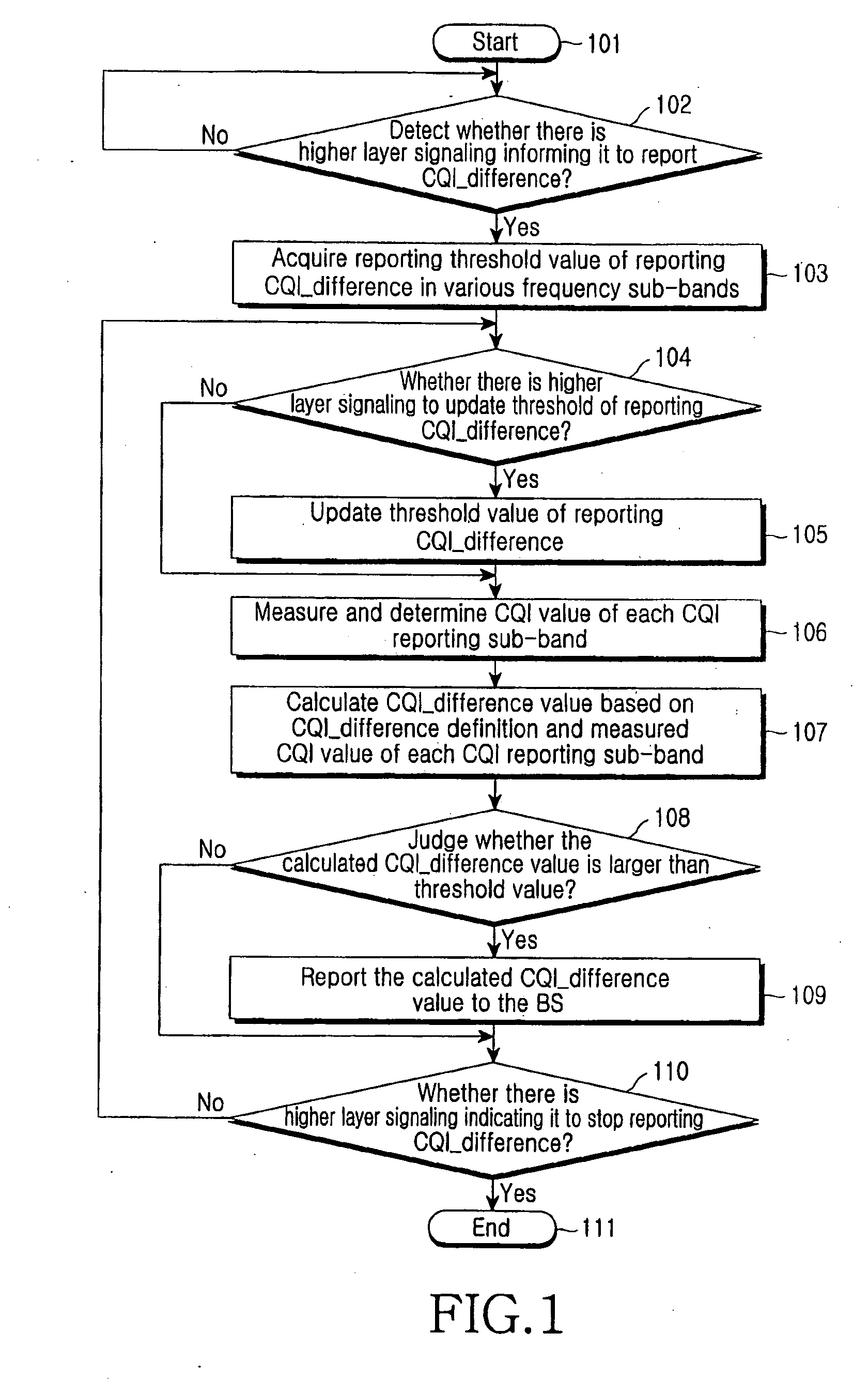
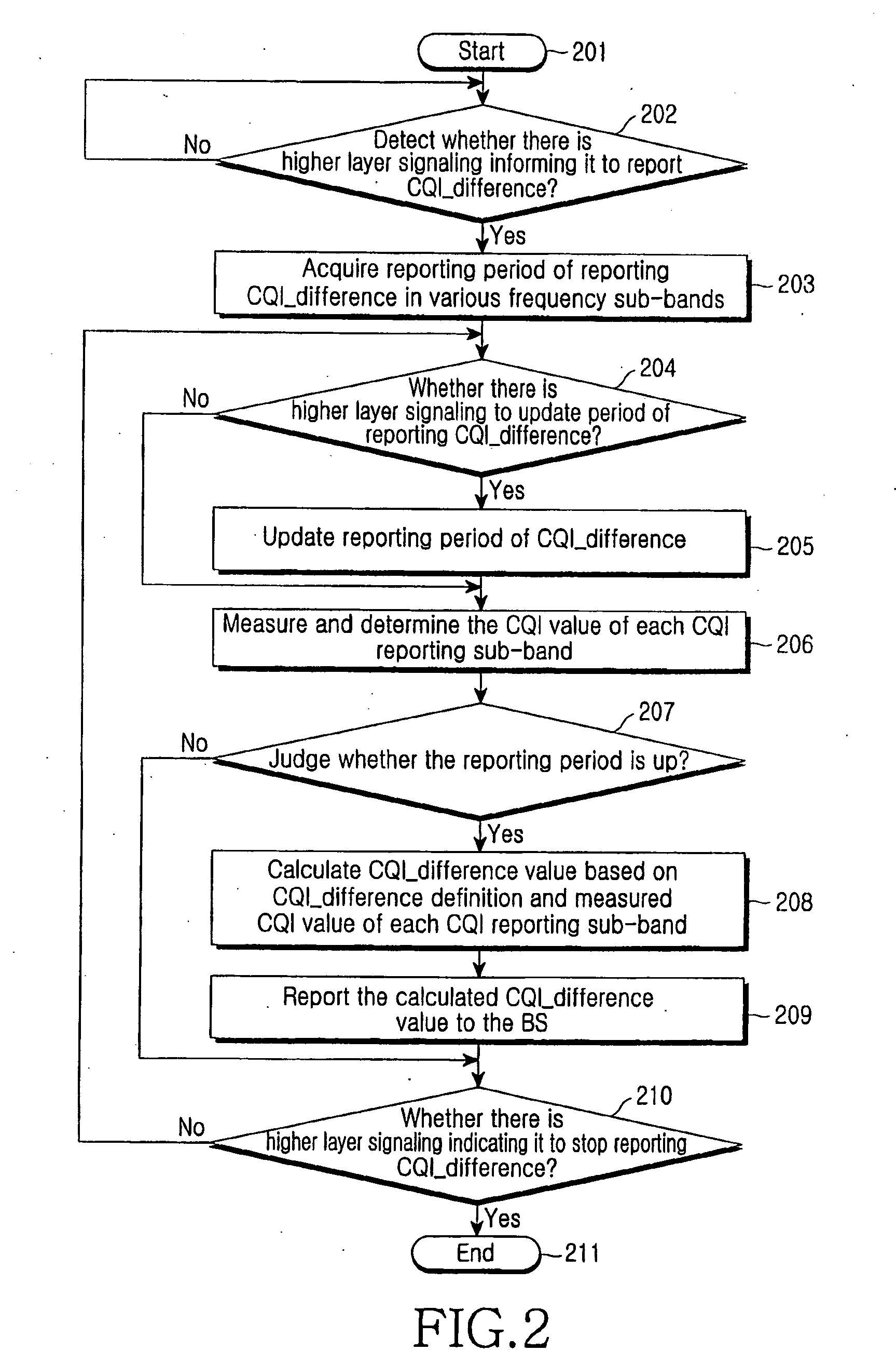
[0032]The present invention provides a method for creating a new measurement report needed by a low speed UE to realize a transition between a localized transmission mode and a distributed mode, such measurement may reflect fading difference of channels between the BS and the UE in CQI reporting sub-bands of various channel quality. If the difference is comparatively large, then the localized transmission mode is more suitable for the corresponding downlink transmission, otherwise, the distributed transmission mode is more suitable. Measurement report CQI_difference, which reflects CQI difference of various CQI reporting frequency sub-bands, may be selected from t...


PUM


Abstract

Disclosed are a method and apparatus for measurement report for the decision of transmission mode transition that obtain a threshold value of reporting CQI_difference of all frequency sub-bands; measure a CQI value at each CQI reporting frequency sub-band of whole frequency band in each measure time interval; determine a CQI_difference value based on the measured CQI value of each CQI reporting frequency sub-band; and compare the determined CQI_difference value with the threshold value, if a condition is satisfied, then the UE sends the determined CQI_difference value to the BS. After the UE has reported this measurement report to the BS, the BS may choose a more suitable data transmission mode for the UE based on this measurement report to make data transmission more effective.

Description

PRIORITY[0001]This application claims priority to an application filed in the Chinese Intellectual Property Office on Dec. 31, 2005, and assigned Serial No. 200510135921.X, and to PCT application PCT / KR2006 / 005833, filed on Dec. 28, 2006, the contents of each which are incorporated herein by reference.BACKGROUND OF THE INVENTION[0002]1. Field of the Invention[0003]The present invention relates to a radio communication system with localized data transmission mode and distributed data transmission mode, and, in particular, to a method for creating a measurement report to determine conversion of transmission mode and apparatus for using the same.[0004]2. Description of the Related Art[0005]The 3rd Generation Mobile Communication System Partnership Project (referred to as 3GPP) standardization organization has commenced on a Long-term Evolution (referred to as LTE) to existing system criteria. Among numerous physical layer transmission techniques, OFDM (Orthogonal Frequency Division Mul...

Claims


Application Information

Patent Timeline
IPC IPC(8): H04B17/00H04L27/26
CPCH04L1/0003H04L5/0007H04L5/0048H04L5/006H04L5/0041H04L5/1453H04L1/003H04L1/0029H04L5/0039H04L5/0094H04B17/00H04W24/00H04L43/06
Inventor SUN, CHENGJUNZHANG, YUJIANSUN, CHUNYINGLI, XIAOQIANGLEE, JU-HO
Owner SAMSUNG ELECTRONICS CO LTD
Learn More