
Inkjet printer head and method to manufacture the same

Inactive Publication Date: 2009-01-08
S PRINTING SOLUTION CO LTD
View PDF8 Cites 11 Cited by
  • Summary
  • Abstract
  • Description
  • Claims
  • Application Information

AI Technical Summary

Benefits of technology

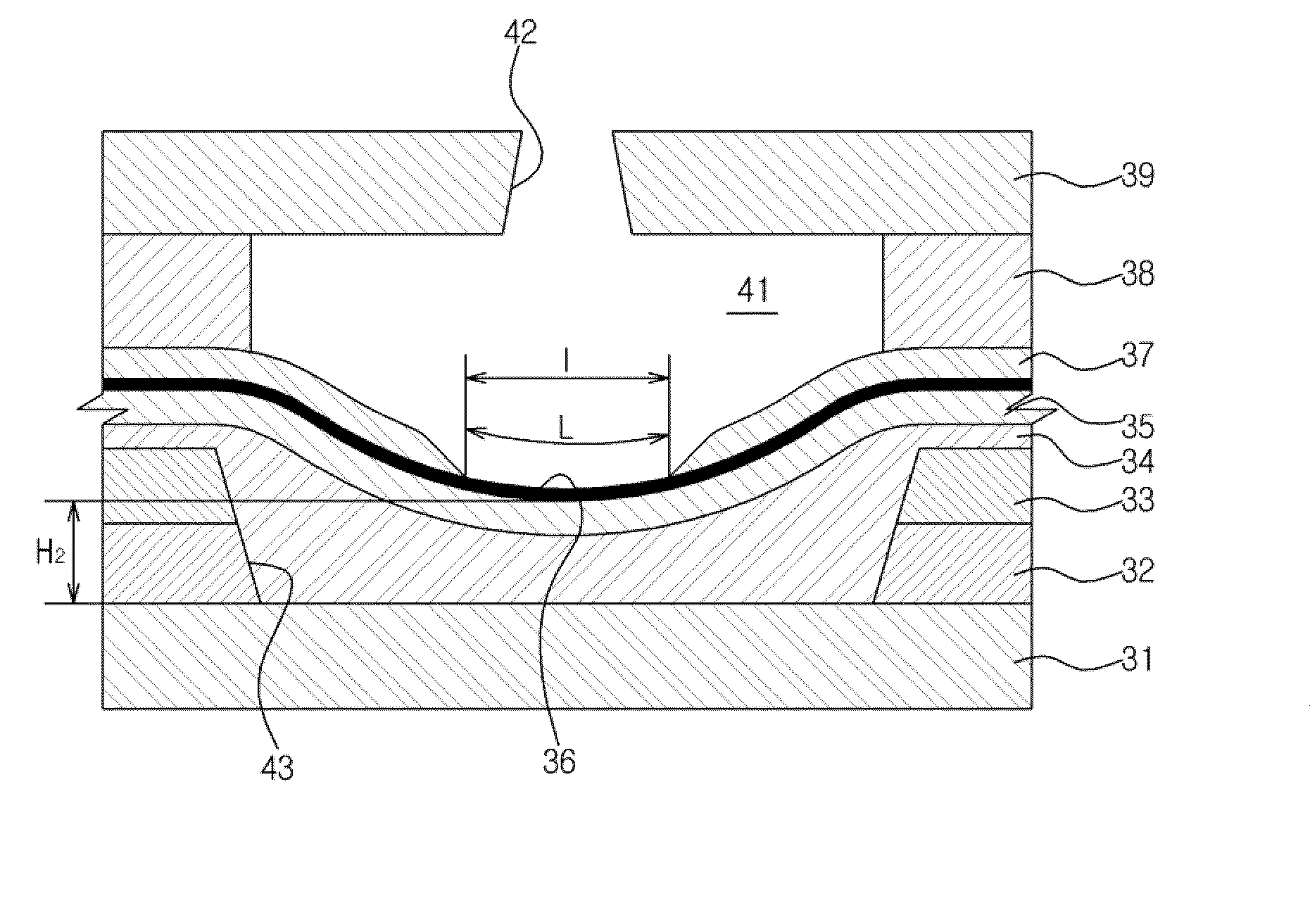
[0019]The present general inventive concept provides an inkjet printer head, to perform the printing regardless of current variation applied thereto by increasing a resistance of a heating member through modifying a shape of a heating member, and a method to manufacture the same.
[0020]The present general inventive concept also provides an inkjet printer head to enable high speed printing by enhancing heat dissipation efficiency of a heating member, and a method to manufacture the same.
[0031]A length of a heating member may increase by allowing the heating member to having a curved structure, so that a resistance of the heating member can be increased. Consequently, the heating member can stably operate regardless of current variation applied thereto.
[0035]Further, according to the inkjet printer head of the present general inventive concept as described above, since a thickness of the insulating layer between the substrate and the heating member is increased, heat dissipation efficiency of the heating member is improved. Consequently, a printing speed can be increased.

Problems solved by technology

Ideal pulse type current is not always applied to such a conventional thermal-driving type inkjet printer head.
That is, when the inkjet printer head is used, a pulse of the electric current applied to the inkjet printer head may irregularly change according to various factors.
With the change in the pulse of the electric current applied to the inkjet printer head, a spraying speed of the ink droplets changes and thus the printing quality may be degraded.
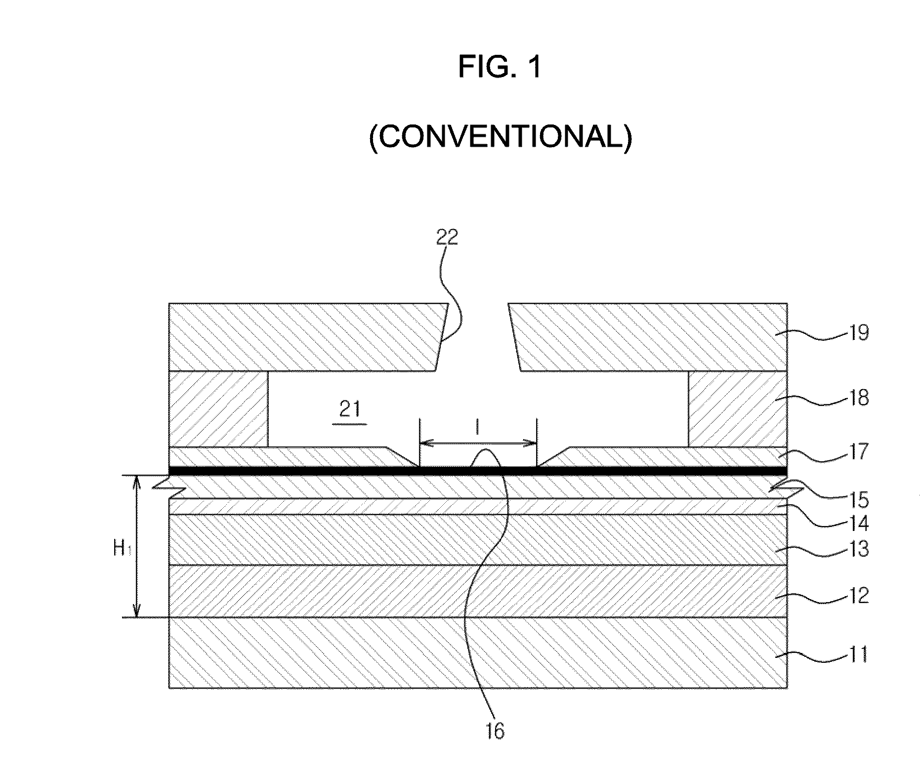
However, since the well-known material suitable for the heating member 16 is limited, new material must be found.
Thus, a development period inevitably increases.
According to the conventional inkjet printer head as described above, if the heat of the heating member 16 is not easily emitted, bubbles are not quickly contracted after the ink droplets are sprayed and thus ink may not be easily supplied to the ink chamber 21.
Therefore, enhancing a printing speed by increasing a frequency of the electric current supplied to the heating member 16 is difficult.

Method used


Image

  • Inkjet printer head and method to manufacture the same
  • Inkjet printer head and method to manufacture the same
  • Inkjet printer head and method to manufacture the same

Examples


Embodiment Construction

[0048]Reference will now be made in detail to embodiments of the present general inventive concept, examples of which are illustrated in the accompanying drawings, wherein like reference numerals refer to the like elements throughout. The embodiments are described below in order to explain the present general inventive concept by referring to the figures.

[0049]As illustrated in FIG. 3, the inkjet printer head according to an embodiment of the present general inventive concept includes a substrate 31, first and second insulating layers 32 and 33, an insulating coating layer 34 and an isolation layer 35 sequentially stacked on the substrate 31, a concave shaped-heating member 36 attached onto the isolation layer 35, an electrode 37 to supply pulse type current to the heating member 36, a chamber layer 38 to form an ink chamber 41 to store ink, and a nozzle layer 39 having a nozzle 42. Hereinafter, the inkjet printer head of the present embodiment will be described in more detail.

[0050...


PUM

PropertyMeasurementUnit
Electrical resistanceaaaaaaaaaa
Distanceaaaaaaaaaa
Distanceaaaaaaaaaa

Abstract

An inkjet printer head includes a substrate, an insulating layer having a groove and disposed on the substrate, a heating member having a concavely curved upper surface and disposed on an upper portion of the groove, an electrode to make contact with the heating member to apply electric current to the heating member, a chamber layer disposed on the heating member, and a nozzle layer having one or more nozzles and disposed on the chamber layer. According to the inkjet printer head, the heating member has a curved structure to increase a length of the heating member, so that resistance of the heating member can be increased. Thus, the heating member can stably operate regardless of current variation applied thereto, and the printing work can be performed.

Description

CROSS-REFERENCE TO RELATED APPLICATIONS[0001]This application claims priority under 35 U.S.C. §119(a) from Korean Patent Application No. 2007-66089, filed on Jul. 6, 2007, in the Korean Intellectual Property Office, the disclosure of which is incorporated herein in its entirety by reference.BACKGROUND OF THE INVENTION[0002]1. Field of the Invention[0003]The present general inventive concept relates to an inkjet printer head. More particularly, the present general inventive concept relates to a thermal-driving type inkjet printer head that sprays ink by using bubbles formed when the ink are heated, and a method to manufacture the same.[0004]2. Description of the Related Art[0005]In general, an inkjet image forming apparatus includes an inkjet printer head that sprays ink based on image signals. The inkjet printer head discharges ink droplets based on the image signals to print characters and figures on a print medium. The image forming apparatuses are classified into a shuttle type i...

Claims


Application Information

Patent Timeline
IPC IPC(8): B41J2/05B23P17/00
CPCB41J2/14129B41J2/1603B41J2/1628Y10T29/49401B41J2/1631B41J2/1645B41J2002/14387B41J2/1629B41J2/01B41J2/015
Inventor PARK, SUNG JOONKIM, TAE-JINPARK, YOUNG HYEKIM, DAI GEUN
Owner S PRINTING SOLUTION CO LTD
Learn More