
Pulling tool

Active Publication Date: 2009-01-08
PULLR HLDG
View PDF24 Cites 9 Cited by
  • Summary
  • Abstract
  • Description
  • Claims
  • Application Information

AI Technical Summary

Benefits of technology

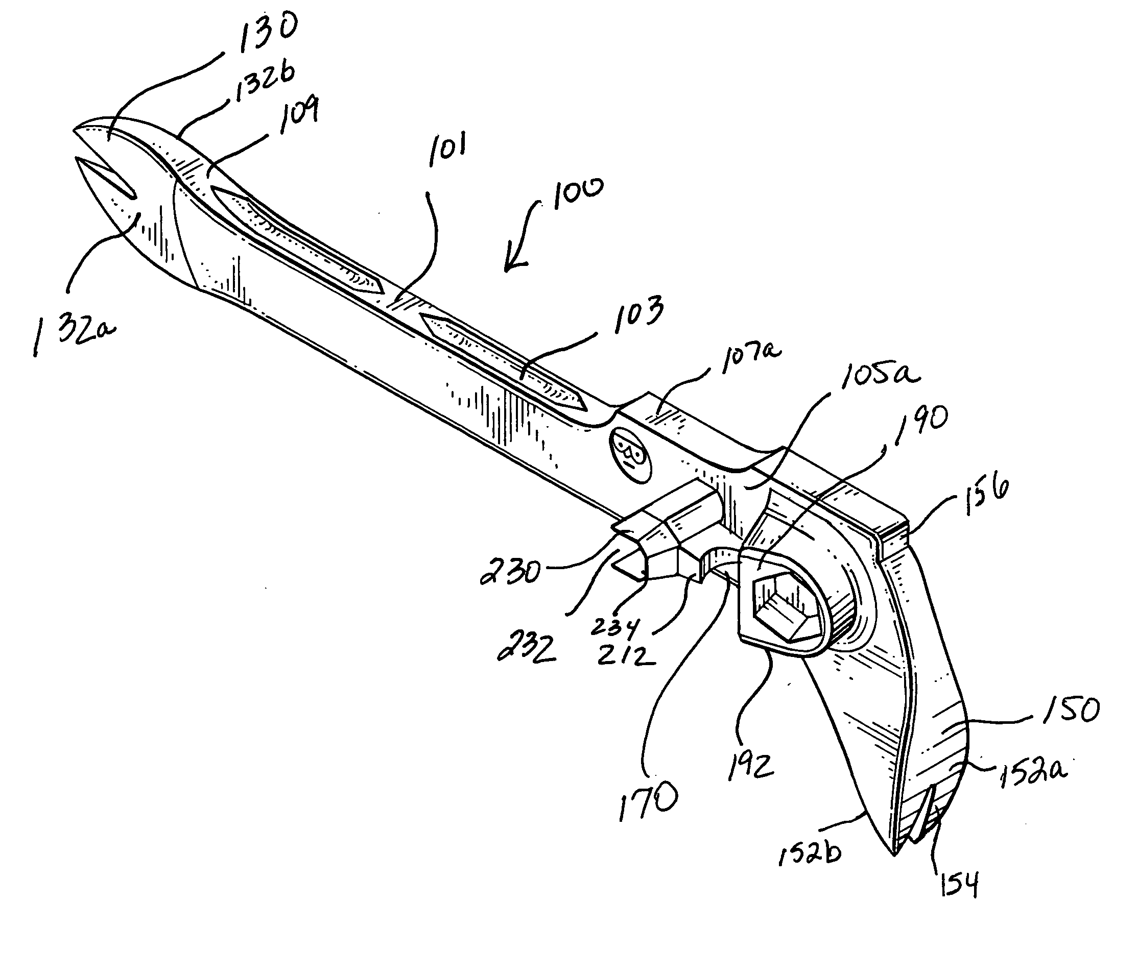
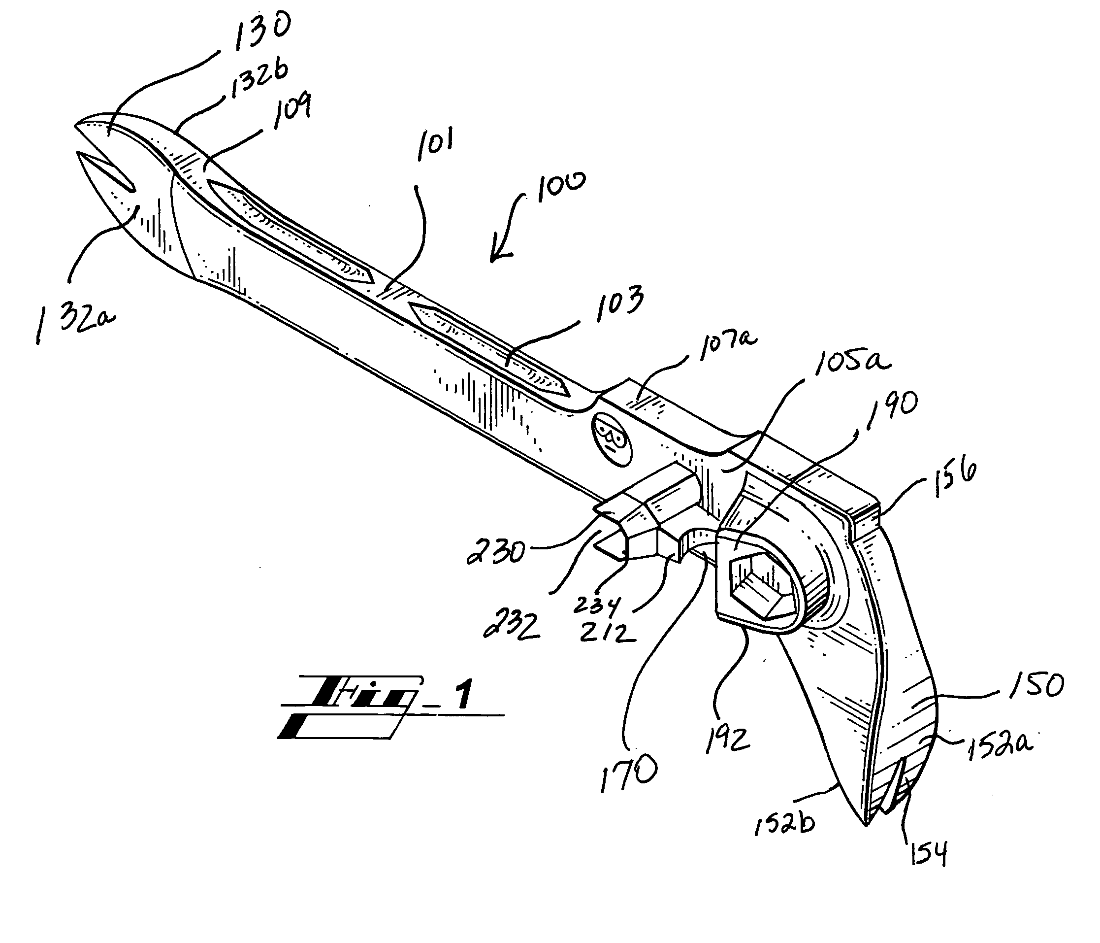
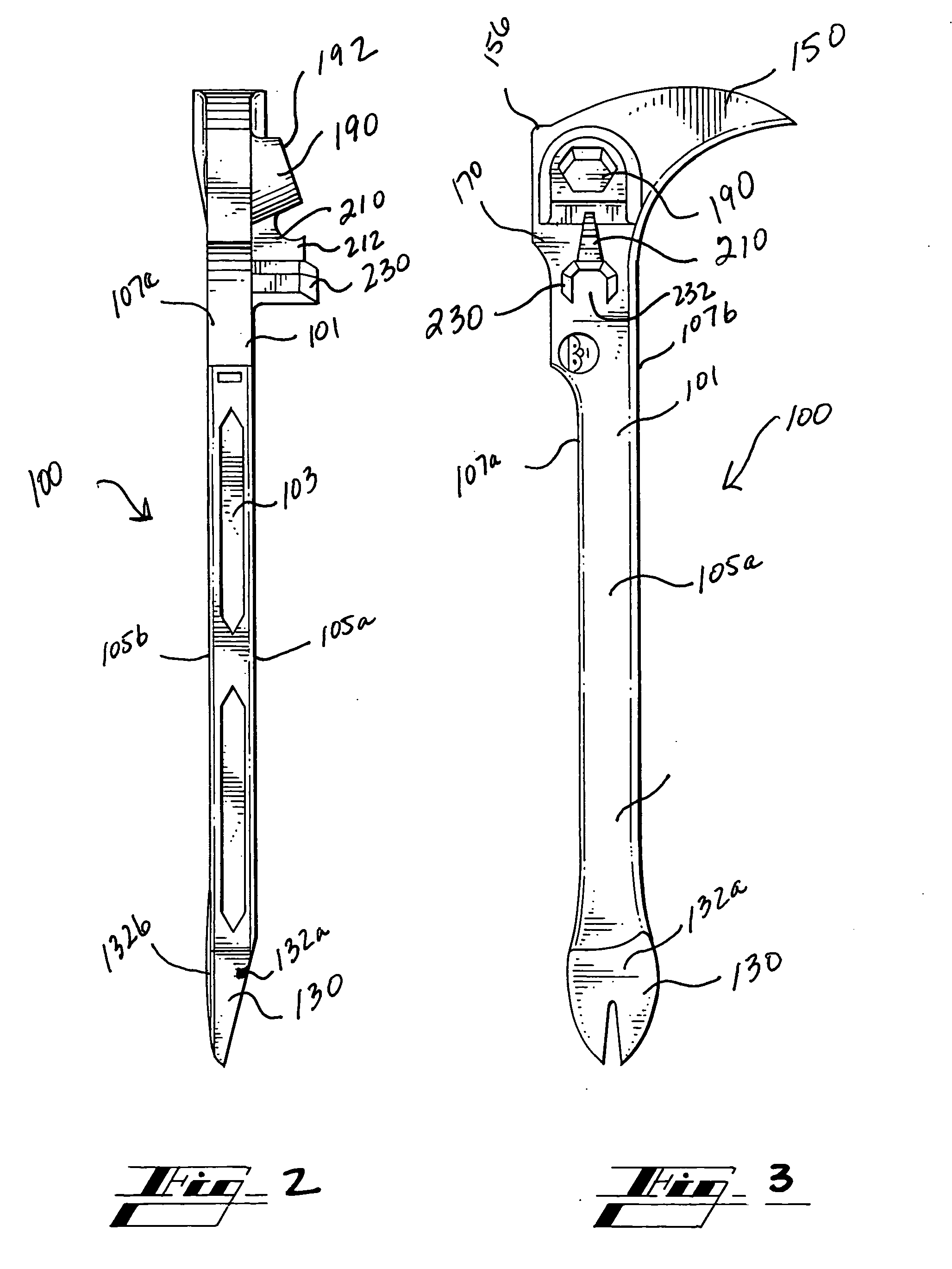
[0008]The nail pick portion is generally a slightly angular extension of the handle and has a preferably broad front and rearward surface, corresponding to the broad, flat side-wall surfaces of the handle, to facilitate effective delivery of prying forces, such as to withdraw nails from a workpiece. The lever pulling head, or non-threaded fastener puller, similarly has a broad front and rearward surface, however, the broadened tine or claw of the pulling surfaces preferably extends dimensionally and angularly from the heel, which corresponds to the narrow edge surfaces of the handle. This facilitates effective delivery of lever action, such as to pull nails firmly embedded in a workpiece. For example, while removal of an improperly positioned nail may require a simple nail pick, some instances of fully seated nails may necessitate the use of a pulling lever claw for beneficial fulcrum action.
[0022]Still another feature and advantage of the tool of the present disclosure is its ability to provide am open wrench that can facilitate the loosening and / or tightening of even deeply recessed bolts.

Problems solved by technology

Thus, each construction worker is often faced with a myriad of tools to transport.
Transport of such a collection of tools to a jobsite is a dubious task in and of itself, but maintaining mobility of such a number of tools and exchanging between tools while working is disadvantageously time and energy consuming.
That is, in addition to time and material costs, worker performance can be compromised by premature exhaustion as a result of repeatedly expending energy exchanging between a plurality of heavy tools, and necessarily transporting those tools about a work site.

Method used


Image

  • Pulling tool
  • Pulling tool
  • Pulling tool

Examples


Embodiment Construction

[0029]In describing exemplary embodiments of the hammer of the present disclosure illustrated in the drawings, specific terminology is employed for the sake of clarity. The claimed invention, however, is not intended to be limited to the specific terminology so selected, and it is to be understood that each specific element includes all technical equivalents that operate in a similar manner to accomplish a similar purpose.

[0030]In that form of the pulling tool of the present disclosure chosen for purposes of illustration, FIGS. 1-3 show tool 100 including handle 101 and grip features 103. Handle 101 is preferably formed from a suitable metal, composite, or synthetic material, or the like, defining nail pick tool 130 and levered pulling head 150, and may include a comfort grip member (not shown) installed thereon. The comfort grip member may be formed from natural or synthetic rubber, plastic, composite, form, combinations, or the like, and may be resilient and / or sculptured or conto...


PUM


Abstract

A multi-function tool having a handle portion and a plurality of structures operable therewith for the performance of a plurality of functions. The multi-function tool allows fast and convenient transition between any of the plurality of functions in order to enable completion of jobs or tasks requiring such functions without acquisition, storage, and / or maintenance of a plurality of specialized tools.

Description

CROSS-REFERENCE TO RELATED APPLICATION[0001]The present U.S. Non-Provisional patent application cross-references and claims priority and benefit as a continuation of co-pending U.S. Design Patent Application Serial No. 29 / 254,444, filed Feb. 23, 2006, entitled “Non-Threaded Fastener Pulling Tool with Saw Wrench, Nail Pick, and Bottle Opener Combination,” which is hereby incorporated by reference in its entirety.TECHNICAL FIELD[0002]The present disclosure relates generally to hand tools, and, more particularly, to construction tools, such as a pulling tool, or the like.BACKGROUND OF THE INVENTION[0003]Construction work typically requires the use of a plurality of tools, including hand tools and electric tools. Necessary hand tools usually include tools designed for joining particular materials together, as well as tools designed to assist in breaking apart construction materials, such as when improper installation or measurement error is detected. Electric tools, such as saws, drills...

Claims


Application Information

Patent Timeline
IPC IPC(8): B25C11/00B25F1/00B67B7/00
CPCB25F1/00B25C11/00
Inventor ADAMS, ROBERTHANLON, JARED
Owner PULLR HLDG
Learn More