
Failure analysis apparatus

a failure analysis and apparatus technology, applied in the direction of fault response, testing circuit, instruments, etc., can solve the problems of large number of hardware failure flags in the entire system board b>100/b>, excessive development effort, and inability to realize the failure analysis function. achieve the effect of reducing the inability to analyze the failure significantly, reducing memory resources, and fast processing

Active Publication Date: 2009-01-01
FUJITSU LTD
View PDF14 Cites 7 Cited by
  • Summary
  • Abstract
  • Description
  • Claims
  • Application Information

AI Technical Summary

Benefits of technology

[0047]The present invention has been made in view of the foregoing circumstances, and for realizing a function of analyzing failures occurred to logic circuits such as LSI mounted on an information processing apparatus, one aspect of an object of the present invention is to provide a new failure analysis technique that realizes a reduction in memory resources, faster processing, and a reduction in labor for the development and that realizes a thorough analysis of critical failures, and further realizing a reduction in an unanalyzable range.

Problems solved by technology

Therefore, an enormous amount of labor for the development is required to realize such a failure analysis function.
Thus, when a large amount of hardware failure flags are set, the conventional analysis processing unit 130 discontinues the failure analysis after a certain number of detections, and reports the failure analysis result up to that point.
There are following problems according to such a conventional art.
(1) Problems in Relation to Memory Resources and Processing Time
However, since several to several tens of ASICs are mounted on the system boards 100, the number of hardware failure flags in the entire system boards 100 is significantly large.
Therefore, there is a problem that a large amount of memory is required for the failure analysis according to the conventional failure analysis method based on every system boards 100.
This also leads to a demand for a large amount of memory resources.
Moreover, the failure analysis is a temporary process executed, when a failure occurs in the system.
However, when the type or the version number of the ASICs is not known in advance, all tables for the ASICs which will be mounted on the information processing apparatus need to be permanently stationed, and a large amount of memory is required for the permanently station.
In this regard too, there is a problem that a large amount of memory resources are required according to the conventional failure analysis method based on every system boards 100.
For this reason, according to the conventional failure analysis method based on every system boards 100, there is a problem that an enormous amount of processing time is required for the failure analysis.
Therefore, according to the conventional failure analysis method based on every system boards 100, labor for the development are generated during the initial design or the modification designs of the tables 110 and 120, and there is a problem that burdens are imposed on the designers.
Therefore, according to the conventional failure analysis method based on every system boards 100, there is a problem that an error occurs due to the difference in recognition.
As described in FIG. 17, the conventional failure analysis method discontinues the failure analysis after a certain number of detections, since the failure flag buffer cannot store the hardware failure flags when a large amount of the hardware failure flags are set.
Therefore, according to the conventional failure analysis method, there is a problem that more critical failures are missed which are detected after the failure flag buffer has become full.
In the conventional failure analysis method based on every system boards 100, as described in FIG. 19, there is a problem that the entire failure analysis of the system boards 100 becomes impossible in a situation such as when the hardware failure flags cannot be collected from even one ASIC mounted on the system boards 100 due to some kind of a secondary problem.

Method used


Image

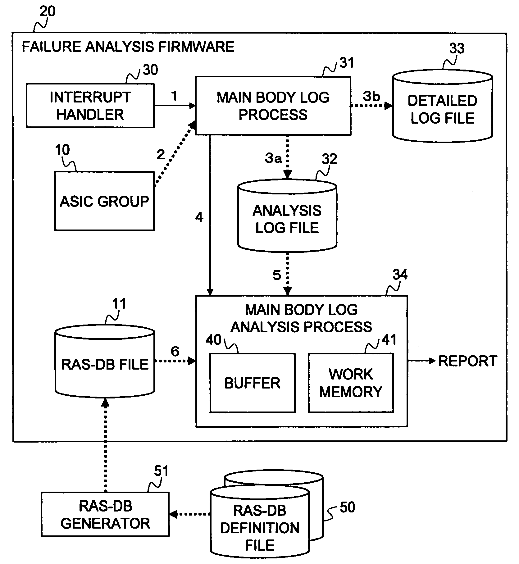
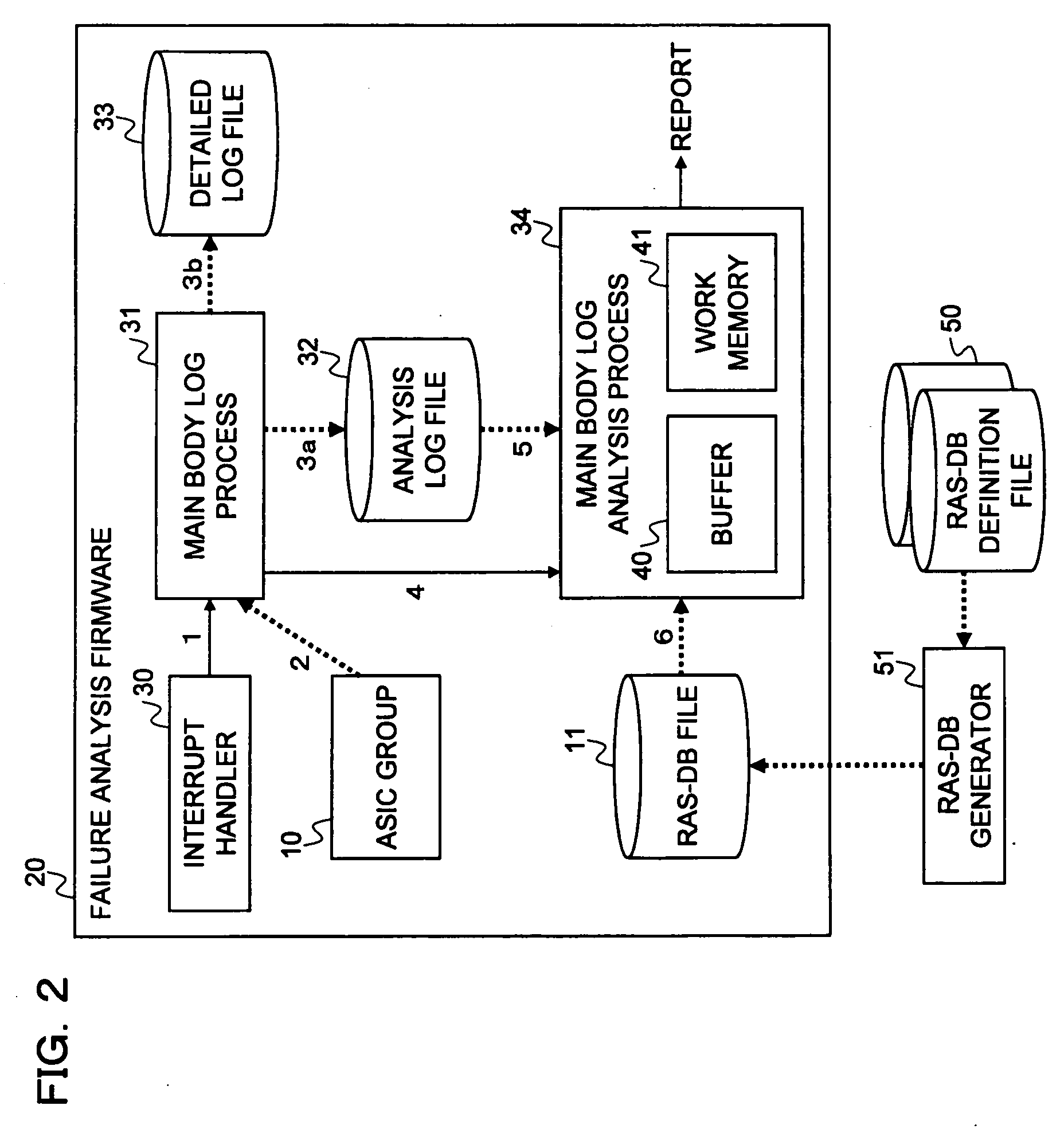
  • Failure analysis apparatus
  • Failure analysis apparatus
  • Failure analysis apparatus

Examples


Embodiment Construction

[0099]The embodiment of the present invention will now be described in detail according to the embodiments.

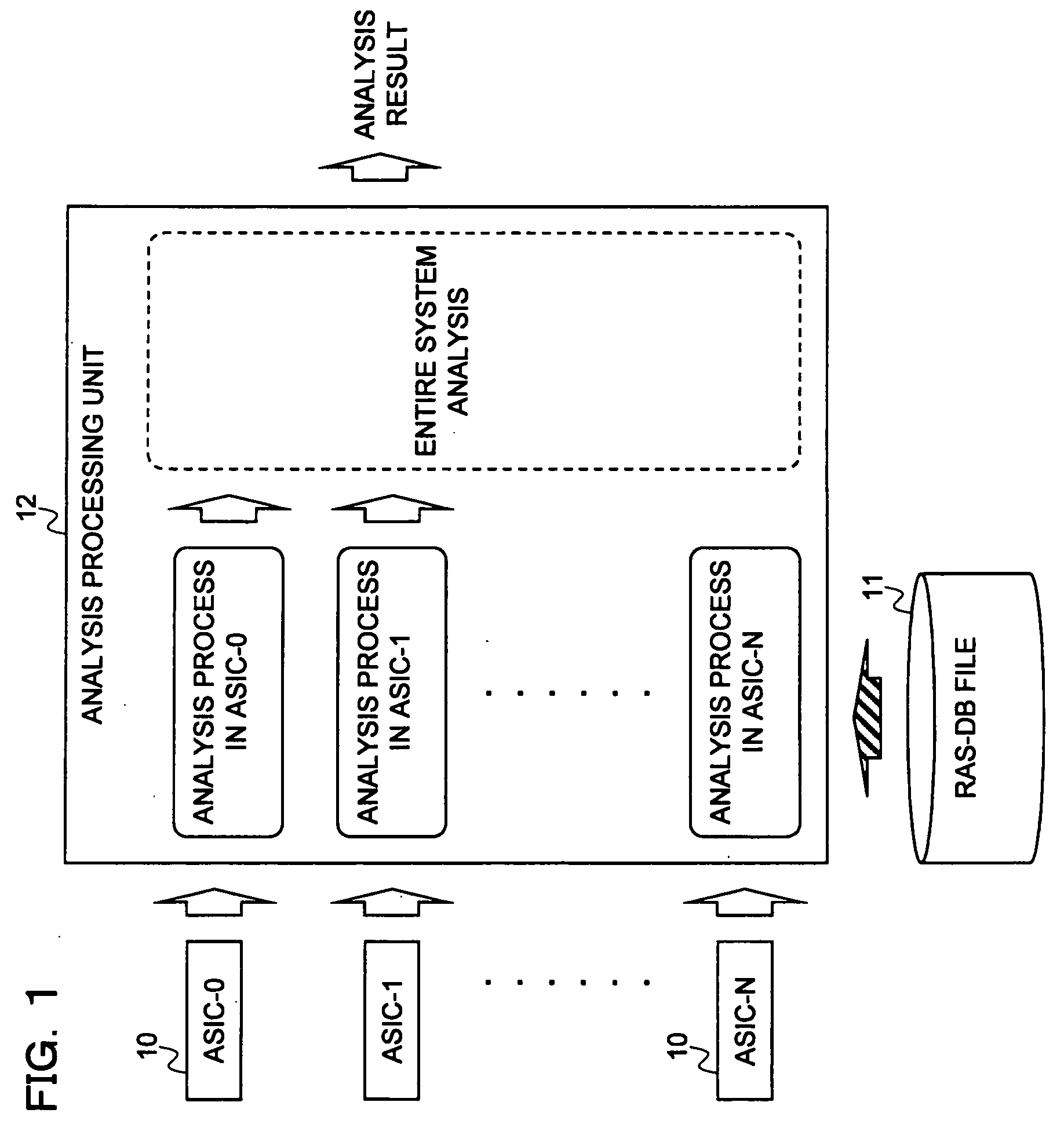
[0100]In the embodiment of the present invention, an information processing apparatus mounted with ASICs executes a process of delivering the analysis result of the entire system by analyzing a failure based on the ASICs when a failure occurs to the ASICs. As a result, it becomes possible to realize the elimination of the failure analysis of the entire system required in the conventional failure analysis that has been performed on every system boards.

[0101]FIG. 1 illustrates a configuration of an embodiment of the present invention that executes the process.

[0102]In FIG. 1, reference numeral 10 denotes N ASICs to be analyzed that are mounted on the information processing apparatus, reference numeral 11 denotes an RAS-DB file, and reference numeral 12 denotes an analysis processing unit.

[0103]The RAS (Reliability Availability Serviceability)-DB file 11 is defined for each of the...


PUM


Abstract

Relating with board numbers of the boards mounted with the logic circuits and mounted places on the boards and in relation to log information to be collected from the logic circuits, analysis information describing information to be processed when the log information is generated, information of a condition for which the log information is to be valid, and information of a condition for which the log information is to be invalid are defined for analyzing failures using the analysis information based on the logic circuits. Upon the realization of the failure analysis based on the logic circuits, the analysis information further describes information of the priority of the log information to realize a thorough analysis of critical failures.

Description

CROSS REFERENCE TO RELATED APPLICATIONS[0001]This is a continuation application of PCT application serial number PCT / JP2006 / 303553, filed on Feb. 27, 2006.BACKGROUND OF THE INVENTION[0002]1. Field of the Invention[0003]An embodiment of the present invention relates to a failure analysis apparatus, which may include a failure analysis apparatus that is implemented in an information processing apparatus having a plurality of boards mounted with a plurality of logic circuits and that analyzes what kind of failure has occurred in the logic circuits to realize a reduction in memory resources, faster processing, and a reduction in labor for development, and to realize a thorough analysis of critical failures, and to realize a reduction in the unanalyzable range.[0004]2. Description of the Related Art[0005]Today, an information processing apparatus is mounted with high-density, integrated, and complicated LSIs such as ASICs (Application Specific Integrated Circuit). In order to reduce a do...

Claims


Application Information

Patent Timeline
Patent Type & Authority Applications(United States)
IPC IPC(8): G06F11/07
CPCG06F11/2268G06F11/079
Inventor NAKAGAWA, MASATO
Owner FUJITSU LTD
Learn More