
Spacer interposed between a blade root and the bottom of a slot in the disk in which the blade is mounted

Active Publication Date: 2009-01-01
SN DETUDE & DE CONSTR DE MOTEURS DAVIATION S N E C M A
View PDF4 Cites 26 Cited by
  • Summary
  • Abstract
  • Description
  • Claims
  • Application Information

AI Technical Summary

Benefits of technology

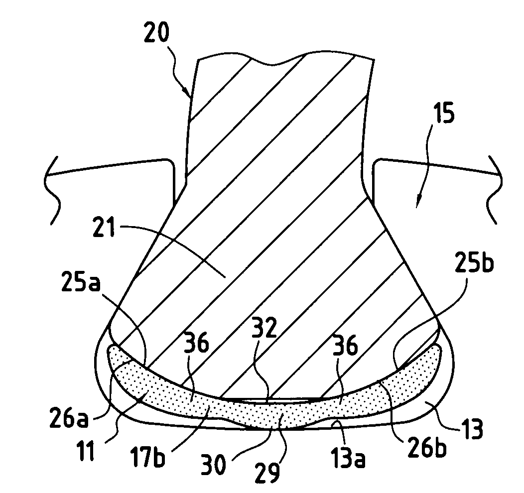
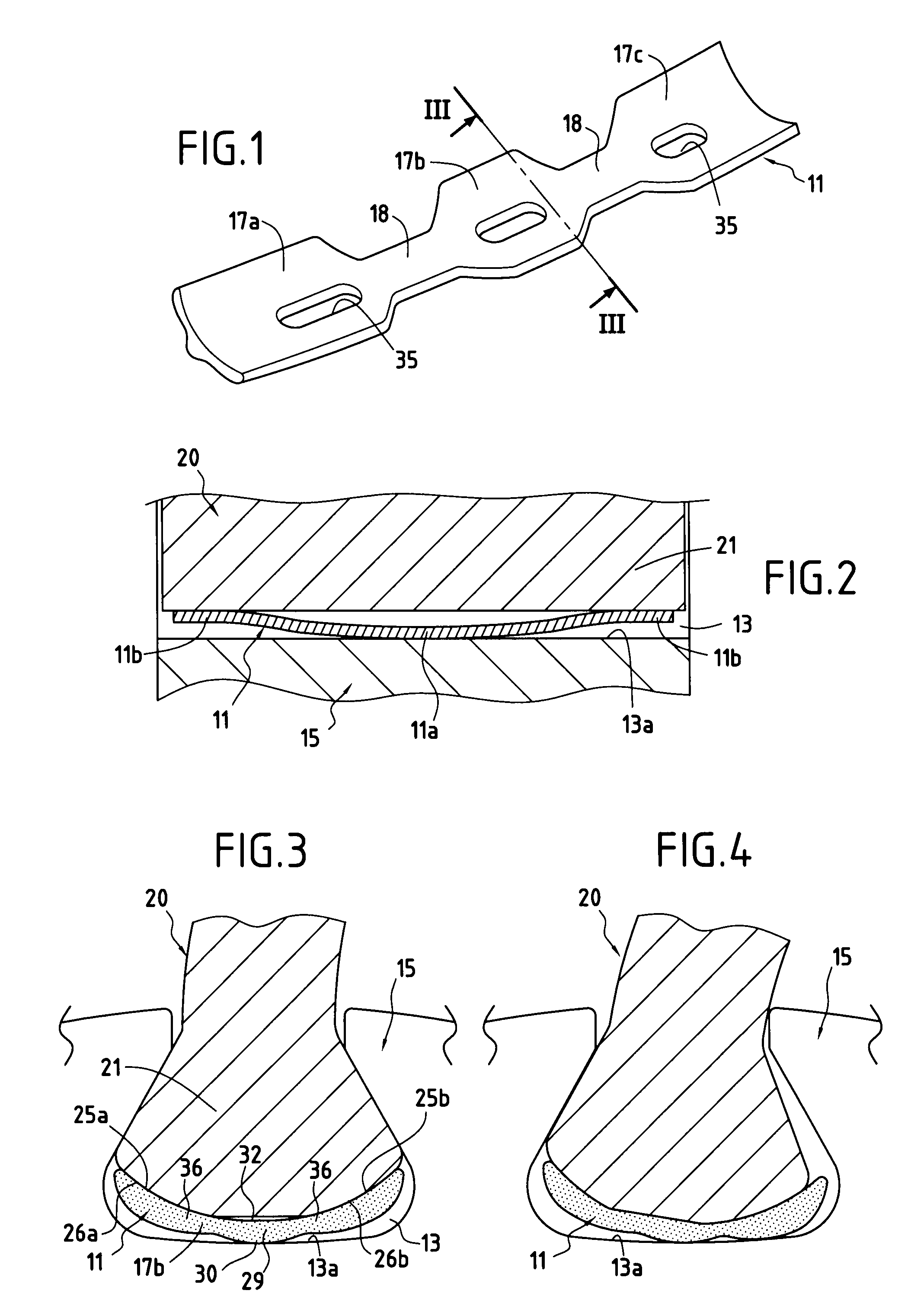
[0010]In addition, in normal operation, the section of the spacer is matched to the shape of the surrounding parts (slot in the fan disk and fan blade), and mounting takes place with a small amount of stress between the blade root and the bottom of the slot. Thus, the blade root is pressed against its bearing surfaces, bearing against the bottom of the slot (in the central portion) and under the blade root against the lateral bearing surfaces thereof. The above-mentioned wave profile serves to optimize contacts between the ends and the center of the spacer, and also between the blade and the disk.
[0011]By virtue of its flexibility, the spacer tracks the combined twisting and plunging movement that occurs during a critical event. It is interposed so as to limit the impact between the blade root and the slot of the disk. In addition, the contact zone between the spacer and the underside of the blade root is of a curved shape so as to enable those two parts to slide relative to each other in the event of the blade pivoting.
[0012]The spacer is preferably subdivided into three sections that respond separately to the combined movements of the blade root, thus enabling the movements and the deformations specific to each of the portions of the blade root to be accompanied as well as possible.
[0013]A coating of the polyurethane film type or the like is placed on and / or under the spacer so as to dissipate a portion of the energy of an impact, and consequently limit any risk of the spacer breaking and of the blade root cracking.

Problems solved by technology

When a blade is made of a composite material comprising a weave that is woven in three dimensions (referred to below as “3D woven”) such impacts run the risk of the blade root cracking and can lead to it breaking, and consequently to the complete loss of the fan blade.

Method used


Image

  • Spacer interposed between a blade root and the bottom of a slot in the disk in which the blade is mounted
  • Spacer interposed between a blade root and the bottom of a slot in the disk in which the blade is mounted

Examples


Embodiment Construction

[0022]In the drawings, there can be seen a spacer 11 for inserting in a slot 13 of a disk 15 of a fan rotor. Such a disk is shown in part only in FIGS. 2 to 4. The spacer 11 is constituted by a single block of elastically deformable material, and more particularly in this example by a block of conventional 3D-woven composite material. The three-dimensional weave defining the core of the part is itself coated in resin.

[0023]As shown, the spacer includes at least one longitudinal segment transverse profile of arcuate shape. In the example shown, three segments 17a, 17b, and 17c of this kind are provided (the number of such segments could be different), which segments are united by narrower junctions 18 of the same material, the segments and the junctions together forming a single part.

[0024]Such a spacer is designed to be inserted in a tangential slot 13 formed in the periphery of the rotor disk 15. In this example, the disk is a fan rotor disk having blades 20 attached thereto. Each ...


PUM


Abstract

Wedging blades attached to the disk of a rotor having slots. According to the invention, each wedging spacer is made of an elastically deformable material and at least one longitudinal segment of the spacer presents a transverse profile of arcuate shape to define two lateral contact zones.

Description

BACKGROUND OF THE INVENTION[0001]The invention relates in general to a turbomachine rotor, and more particularly to a fan rotor comprising a disk with slots in its periphery and respective blades attached to said rotor, each blade having a blade root engaged in a corresponding slot. The invention relates to an improvement of an elongate spacer that is interposed between the blade root and the bottom of the slot. The invention applies particularly to mounting blades made of 3D-woven composite material, of the kind that are being used more and more in fans. The invention relates to a spacer that is well adapted to this type of blade (although not exclusively so), the spacer itself possibly being made of a material that is the same or similar. One of the objects of the invention is to improve the behavior of the blades of a rotor, in particular a fan rotor, in the event of a serious incident, e.g. as a result of ingesting a bird.[0002]It is known to insert a deformable spacer in each s...

Claims


Application Information

Patent Timeline
IPC IPC(8): F01D5/30F01D5/02
CPCF01D5/3092F04D29/322F01D5/303F04D29/668F04D29/666
Inventor BELMONTE, OLIVIERGOGA, JEAN-LUC CHRISTIAN YVONMAHIEU, JEAN-NOEL
Owner SN DETUDE & DE CONSTR DE MOTEURS DAVIATION S N E C M A
Learn More