Body-Side Suspension Strut Bearing For Wheel Suspensions
- Summary
- Abstract
- Description
- Claims
- Application Information
AI Technical Summary
Benefits of technology
Problems solved by technology
Method used
Image

Examples
Embodiment Construction
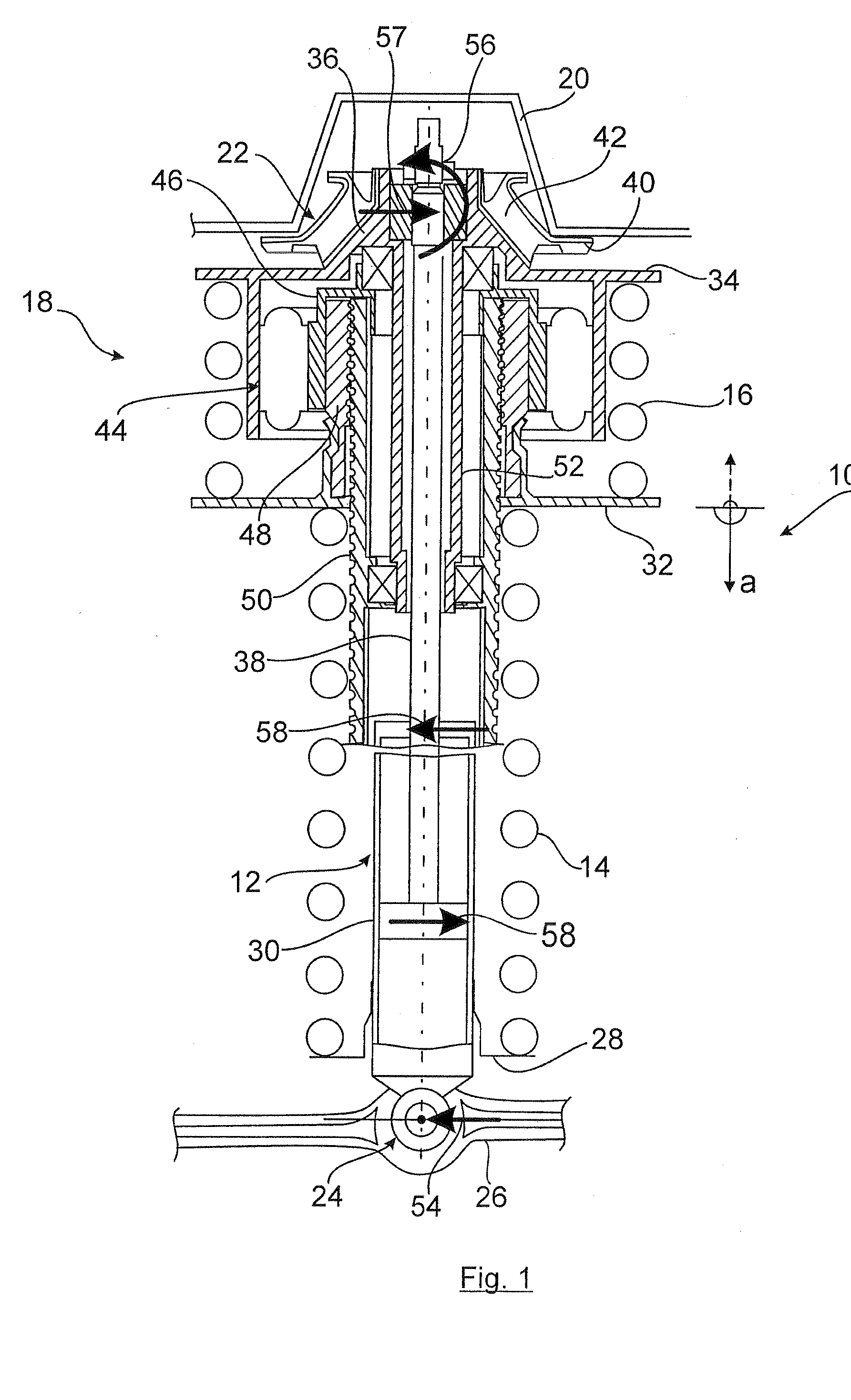
[0020]FIG. 1 shows a suspension strut 10 which corresponds to the prior art according to DE 10 2005 001 744 B3, with a telescoping shock absorber 12, a bearing spring 14 which is formed by a helical compression spring, a compensating spring 16 and a height adjustment device 18.
[0021]The suspension strut 10 as a part of the wheel suspension for a motor vehicle on the one hand is coupled to the body 20 by way of a shock absorber bearing 22 and on the other hand via a rubber-metal bush bearing 24 to a suspension arm 26 as the wheel suspension element of the wheel suspension.
[0022]The bearing spring 14 is firmly supported on its lower end via a spring plate 28 on the tube 30 of the shock absorber 12 and on its upper end adjoins the axially movable spring plate 32.
[0023]The compensating spring 16 which is likewise made as a helical compression spring is clamped between the spring plate 32 and the upper spring plate 34, the spring plate 34 being supported on the shock absorber bearing 22 ...
PUM
 Abstract
Description
Claims
Application Information
 - R&D
- Intellectual Property
- Life Sciences
- Materials
- Tech Scout
- Unparalleled Data Quality
- Higher Quality Content
- 60% Fewer Hallucinations
Browse by: Latest US Patents, China's latest patents, Technical Efficacy Thesaurus, Application Domain, Technology Topic, Popular Technical Reports.
© 2025 PatSnap. All rights reserved.Legal|Privacy policy|Modern Slavery Act Transparency Statement|Sitemap|About US| Contact US: help@patsnap.com