
Light Guide Device and Back Lighting Module Comprising the Same

Inactive Publication Date: 2009-01-01
SEOUL SEMICONDUCTOR
View PDF9 Cites 6 Cited by
  • Summary
  • Abstract
  • Description
  • Claims
  • Application Information

AI Technical Summary

Benefits of technology

[0009]Accordingly, an object of the present invention is to provide a light guide device capable of mixing different colored light emitted from LEDs and transferring the mixed light to a display panel, wherein the colors of light can be more uniformly mixed and a light loss occurring upon mixing of the colors of light can be minimized.
[0010]Another object of the present invention is to provide a back lighting module including a plurality LEDs for emitting different colored light and a light guide device for mixing the light emitted from the LEDs and transferring the mixed light to a display panel, wherein the light guide device is constructed such that the colors of light can be more uniformly mixed and there is few light loss during the mixing of the light.
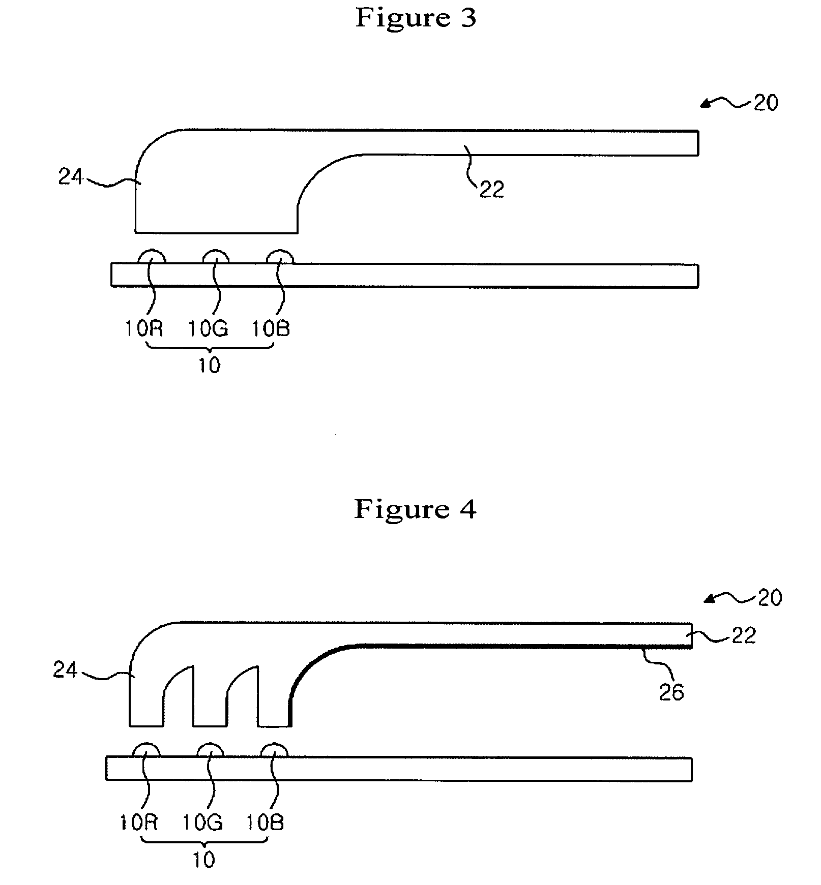
[0011]In order to achieve the objects, the present invention provides a light guide device for mixing different colored light emitted from a plurality of light emitting diodes (LEDs) and guiding the mixed light to a display panel, wherein the light guide device comprises a light guide portion in the form of a plate arranged at a rear of the display panel; and a light mixing portion formed integrally with the light guide portion and including a light incidence surface adjacent to the plurality of LEDs and a light mixing area for mixing the light with difference colors incident through the light incidence surface. Thus, when the light guide device of the present invention illuminates a display panel using the different colored light received from the plurality of LEDs, the light guide device can sufficiently mix the different colored light in the light mixing portion. In addition, since the light guide device sufficiently mixes the different colored light with few light loss while the light is transferred from the light mixing portion to the light guide portion, there is an advantage in that the mixed high-quality light can be supplied to the display panel.

Problems solved by technology

In addition, displays, which have been limitedly used for home appliances such as TVs, expand their applications to a variety of electronic devices such as information communication devices.
However, since such a back lighting module is constructed such that different colored light emitted from the LEDs are oriented directly to the LCD panel through the light guide plate, there is a problem in that insufficiently and unevenly mixed light is provided to the LCD panel.
Particularly, in a case where it is intended to illuminate the LCD panel by using white light obtained by mixing red, green and blue light with one another, the uneven mixing of light becomes an obstruction to implementation of high-quality white light.
However, since the light should pass through the reflecting space where air exists while being transferred from the light mixing plate to the light guide plate in the conventional back lighting module, a light loss increases, resulting in degradation of the transfer efficiency of light and thence considerable degradation of the energy efficiency of the LEDs.

Method used


Image

  • Light Guide Device and Back Lighting Module Comprising the Same
  • Light Guide Device and Back Lighting Module Comprising the Same
  • Light Guide Device and Back Lighting Module Comprising the Same

Examples


Embodiment Construction

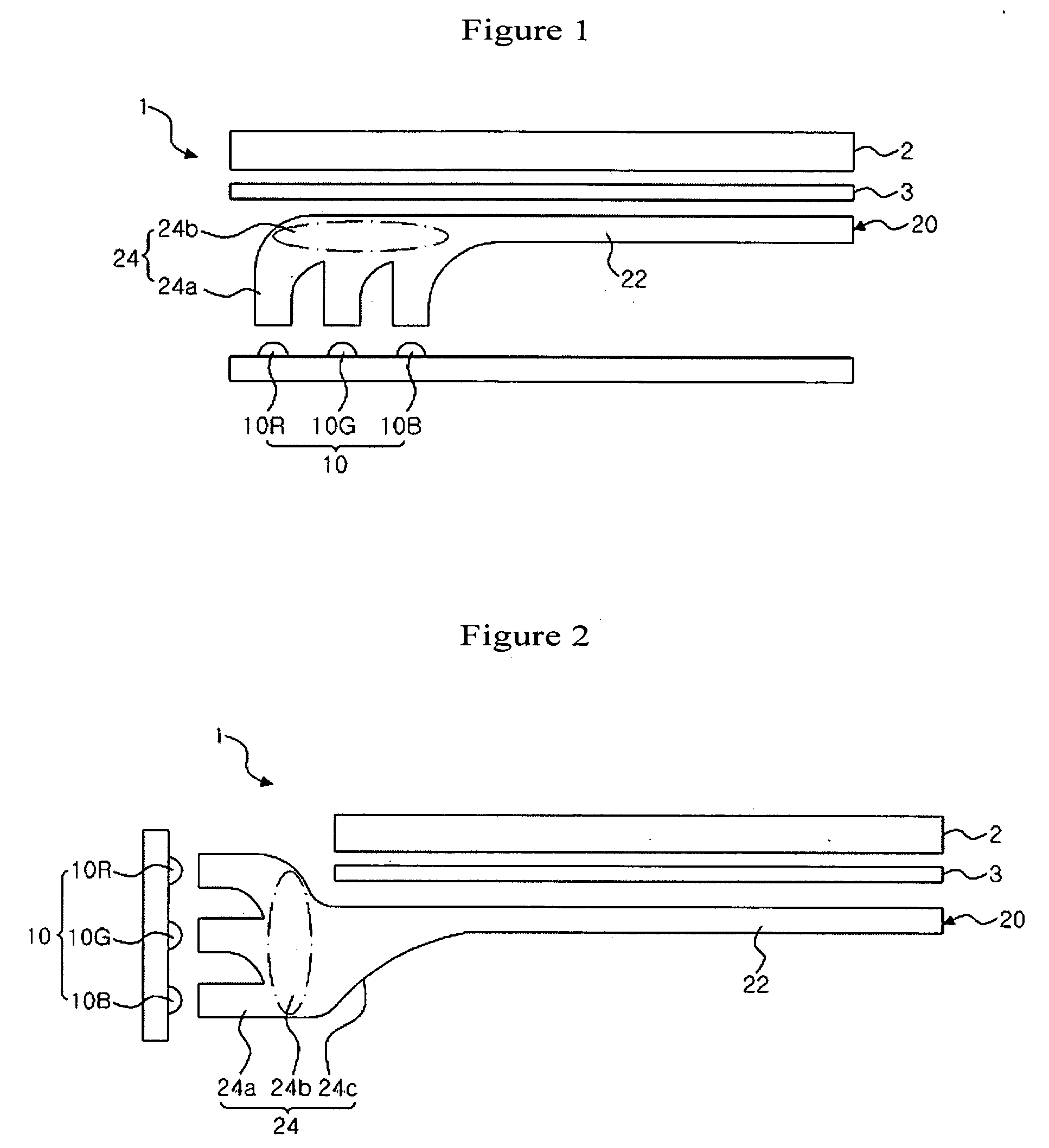
[0023]FIG. 1 is a schematic diagram showing a back lighting module according to an embodiment of the present invention together with an LCD panel.

[0024]As shown in FIG. 1, the back lighting module 1 of this embodiment comprises an LED array 10 including a plurality of LEDs 10R, 10G and 10B, and a light guide device 20 for receiving and mixing different colored light from the LED array 10 and guiding the mixed light to an LCD panel 2.

[0025]In this embodiment, the LED array 10 includes the plurality of LEDs 10R, 10G and 10B for respectively generating red, green and blue (RGB) light. In addition, an LED array of a white light source may also be applied. At this time, the LED array 10 is provided locally at a side portion on a substrate.

[0026]The light guide device 20 is an essential feature of the present invention, and functions to receive and mix different colored light from the plurality of LEDs 10R, 10G and 10B and subsequently to guide the mixed light to the LCD panel 2. The ligh...


PUM


Abstract

A light guide device is used in a back light module that more uniformly mixes different colored light emitted from a plurality of LEDs and transfers the mixed light to a display panel, wherein a light loss can be minimized during the light mixing process and the light can be more uniformly mixed. A light guide device is disclosed for mixing different colored light emitted from a plurality of light emitting diodes (LEDs) and guiding the mixed light to a display panel, wherein the light guide device comprises a light guide portion in the form of a plate arranged at a rear of the display panel; and a light mixing portion formed integrally with the light guide portion and including a light incidence surface adjacent to the plurality of LEDs and a light mixing area for mixing the light with difference colors incident through the light incidence surface.

Description

CROSS REFERENCE TO RELATED APPLICATIONS[0001]This application is the National Stage of International Application No. PCT / KR2006 / 005428, filed on Dec. 13, 2006, and claims priority from and the benefit of Korean Patent Application No. 10-2005-0135033, filed on Dec. 30, 2005, which are both hereby incorporated by reference for all purposes as if fully set forth herein.BACKGROUND OF THE INVENTION[0002]1. Field of the Invention[0003]The present invention relates to a light guide device for mixing light of various colors and guiding the mixed light to a display panel, and a back lighting module comprising the light guide device.[0004]2. Discussion of the Background[0005]Recently, information communication devices such as computers, mobile phones and portable information terminals are actively developed. In addition, displays, which have been limitedly used for home appliances such as TVs, expand their applications to a variety of electronic devices such as information communication devic...

Claims


Application Information

Patent Timeline
IPC IPC(8): F21V7/04
CPCG02B6/002G02B6/0031G02B6/0038G02B6/0055G02F1/133615G02B6/0073G02F1/133603G02F1/133609G02B6/0068G02F1/1335
Inventor LEE, SANG MINRYU, SEUNG RYEOLKANG, SEOK JINCHO, JAE HO
Owner SEOUL SEMICONDUCTOR
Learn More