
Foldable Composite Panel with Compression Relief Hinge

Inactive Publication Date: 2009-01-01
HOLLEY JR JOHN M
View PDF8 Cites 5 Cited by
  • Summary
  • Abstract
  • Description
  • Claims
  • Application Information

AI Technical Summary

Benefits of technology

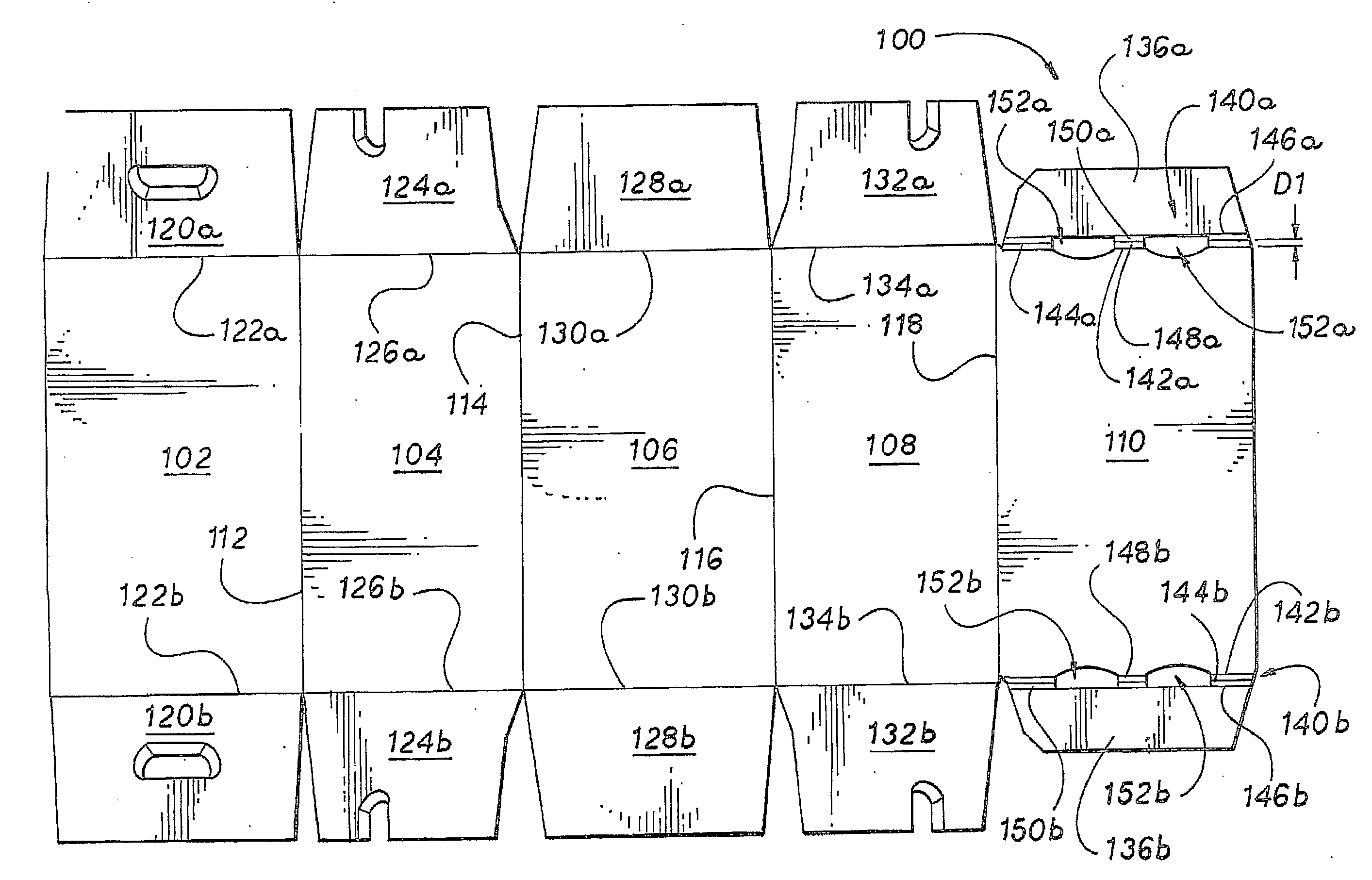
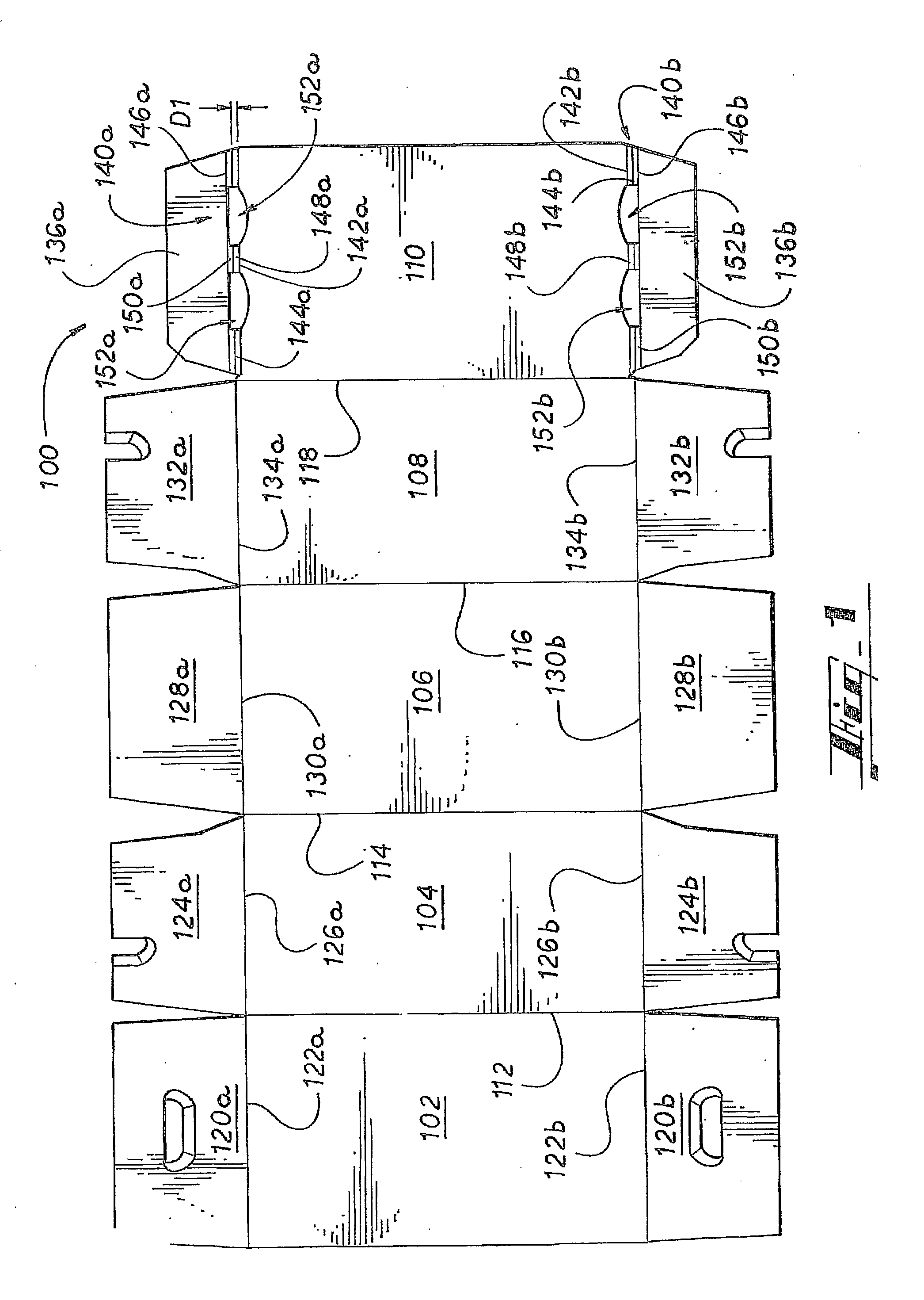
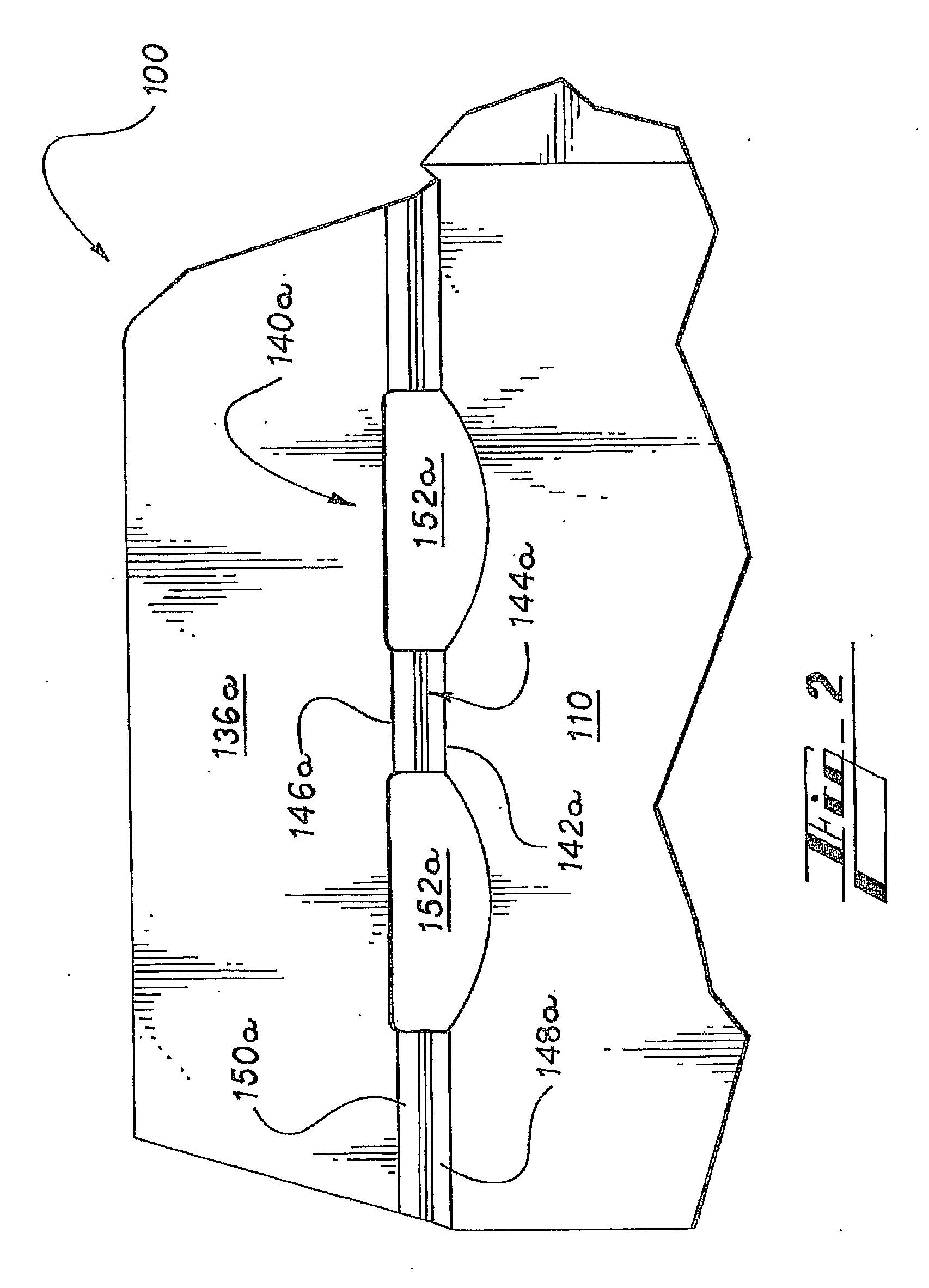
[0005]The various embodiments of the present invention overcome the shortcomings of the prior art by providing a multi-layer or composite panel with an arrangement of overlying aligned hinges, including a compression relief hinge and a primary hinge, that facilitate folding the composite panel. The compression relief hinge is formed in one of the layers of the composite panel and, as the composite panel is folded along the primary hinge, the compression relief hinge bulges away from the primary hinge to reduce congestion in the folding area. Thereby, the thickness of the material in the area where the composite panel is folded is essentially reduced and the composite panel can be easily folded along the primary hinge.
[0009]Further, in certain embodiments, the dimensions of the fold lines that define the compression relief hinge are functions of the thicknesses of the layers of the composite panel. The medial and distal fold lines can have widths and depths such that the bulge panels or otherwise the material of the compression relief hinge can collapse the cavities defined by the medial and distal fold lines as the compression relief hinge is folded along the fold lines. The collapsing of the cavities facilitates folding the bulge panels or otherwise the furrowing of the compression relief hinge. In such embodiments, the cavity of each of the distal fold lines can be formed in a first surface or side of the reinforcing layer and the cavity of the medial fold line can be formed in a second surface or side of the reinforcing layer.
[0010]In certain embodiments, the width of the medial fold line is greater than the width of the distal fold lines. A wider fold line is typically easier to buckle, collapse, or initiate a fold along. To form a wider medial fold line, in certain embodiments, the medial fold line is formed from a group of three or more substantially parallel weakened lines that are substantially adjacent to one another or otherwise directly abutting one another. The group of weakened lines cooperates such that the medial fold line collapses when the composite panel is folded. To that end, at least one in the group of weakened lines is comparatively weaker than the other score lines in the group. In other words, the comparatively weaker weakened line can be folded more easily than the others, and thus, defines the preferred location of the inward collapse of the medial fold line. The comparatively weaker weakened line is made more easily foldable by means of any composition, arrangement, combination, or series of at least one slit, cut, half cut, deep score, crimp, or perforation.

Problems solved by technology

The folding resistance caused by the tension and compression causes multiple problems including cracking or other damage to the primary and / or reinforcing layer, an irregular or otherwise aesthetically unappealing corner of the carton, and interference with the ability of a machine to fold the composite panel during the packaging process.

Method used


Image

  • Foldable Composite Panel with Compression Relief Hinge
  • Foldable Composite Panel with Compression Relief Hinge
  • Foldable Composite Panel with Compression Relief Hinge

Examples


Embodiment Construction

[0019]As required, detailed embodiments of the present invention are disclosed herein. It must be understood that the disclosed embodiments are merely exemplary of the invention that may be embodied in various and alternative forms, and combinations thereof. As used herein, the word “exemplary” is used expansively to refer to embodiments that serve as illustrations, specimens, models, or patterns. The figures are not necessarily to scale and some features may be exaggerated or minimized to show details of particular components. In other instances, well-known components, systems, materials, or methods have not been described in detail in order to avoid obscuring the present invention. Therefore, specific structural and functional details disclosed herein are not to be interpreted as limiting, but merely as a basis for the claims and as a representative basis for teaching one skilled in the art to variously employ the present invention.

[0020]Referring now to the drawings in which like...


PUM


Abstract

According to an exemplary embodiment, a composite panel includes a primary layer (102, 120a) that includes a primary hinge (122a). The primary hinge (122a) is defined by at least one fold line. The composite panel further includes a reinforcing layer (110, 136a) that includes a compression relief hinge (140a). The compression relief hinge (140a) is defined by a pair of distal fold lines (142a, 146a) and a medial fold line (144a) that Is disposed between and spaced apart from the distal fold lines (142a, 146a). The primary hinge (122a) overlies the compression relief hinge (140a) so that when the composite panel is folded about the primary hinge (122a), the composite relief hinge (140a) buckles away from the primary hinge (122a).

Description

CROSS REFERENCE TO RELATED APPLICATIONS[0001]This application claims priority to U.S. Provisional Application No. 60 / 754,929, filed Dec. 29, 2005, the entirety of which is incorporated herein by reference.TECHNICAL FIELD[0002]This invention relates generally to packaging, and in particular, to cartons that include multi-layer panels that are folded to form a corner of a carton.BACKGROUND OF THE INVENTION[0003]Stronger carton walls are desirable for securely packaging items and for transporting heavy items. One method of strengthening selected walls or portions of a carton is to thicken them. For example, a reinforcing layer can be attached to a primary layer to form a composite panel that defines one or more composite walls or portions of the carton. However, the increased thickness of such a composite panel creates increased folding resistance when folding the composite panel, for example, to form a corner of the carton.[0004]The increased folding resistance is due to portions of t...

Claims


Application Information

Patent Timeline
IPC IPC(8): B65D5/08B31B50/25
CPCB31B2201/25B65D5/4608B65D5/4266B65D5/0227B31B50/25
Inventor HOLLEY, JR., JOHN M.
Owner HOLLEY JR JOHN M
Learn More