
Blood Collection Assembly

a technology of blood collection and assembly, which is applied in the field of medical needle devices and assembly, can solve the problems of difficult alignment, engagement and other assembly of devices, and achieve the effect of convenient manufacturing, engagement and assembly

Active Publication Date: 2008-12-25
BECTON DICKINSON & CO
View PDF38 Cites 40 Cited by
  • Summary
  • Abstract
  • Description
  • Claims
  • Application Information

AI Technical Summary

Benefits of technology

[0011]A need exists for a blood collection assembly that includes the requisite components, where these components are easily manufactured, engaged and assembled in a safe and efficient manner.
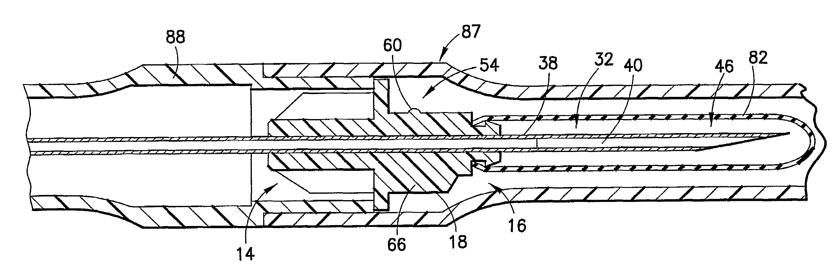
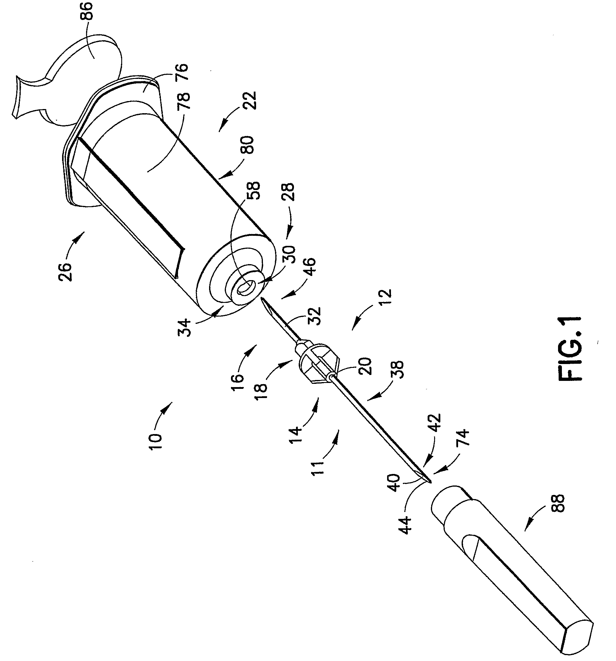
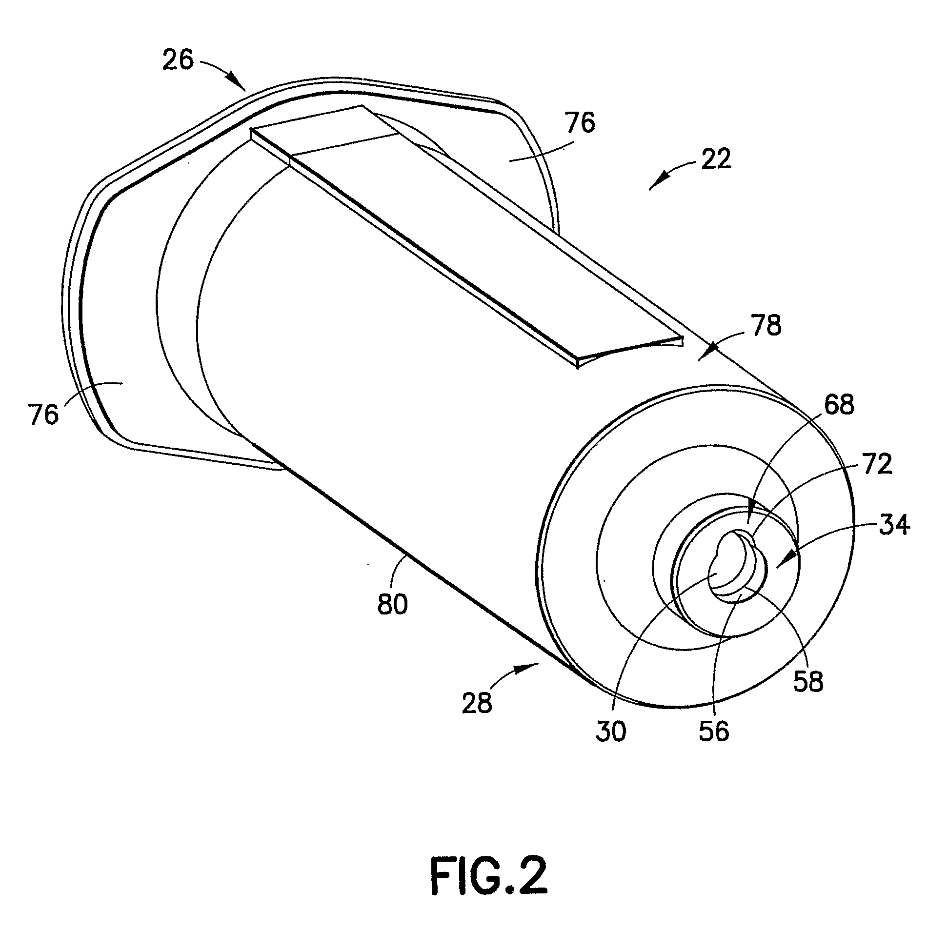
[0012]Accordingly, an embodiment of the present invention provides a blood collection assembly comprising a holder housing defining a receiving chamber and including a rearward end adapted to receive a sample collection tube within the chamber and a forward end including a receiving port extending into the chamber. The assembly further comprises a hub including a hub outer surface extending between a distal end and a proximal end, an internal opening extending therethrough and a puncturing element at the proximal end thereof. The hub is received within the receiving port of the holder housing such that at least a portion of the hub outer surface engages a corresponding interior surface of the receiving port. The hub is maintained within the receiving port through interfering structure extending substantially perimetrically between the hub outer surface and the interior surface of the receiving port. In this manner, a snap-fit engagement axially locks the hub to the holder housing with the puncturing element of the hub extending through the receiving port and into the chamber of the holder housing for contact with a sample collection tube received within the chamber. The engagement between the hub outer surface and the corresponding receiving port interior surface provides support against torque applied to the distal end of the hub, preventing release of the snap-fit engagement established through the interfering structure between the hub outer surface and the receiving port interior surface.
[0015]Moreover, the assembly may include structure for preventing rotational movement of the hub within the receiving port. For example, the hub outer surface may comprise an anti-rotation element to prevent rotational movement of the hub within the receiving port. For example, the hub outer surface may include a nub extending from the outer surface at the proximal end, and the receiving port may be sized and shaped so as to receive and substantially abut the nub, such as through a notch portion configured to receive and substantially abut an outer surface of the nub. Moreover, the outer surface of the nub may be rounded and configured for ease of insertion within and abutment against a complimentary rounded internal surface of the notch portion of the receiving port.

Problems solved by technology

Prior art devices such as those noted typically involve complex engagement systems between the hub and / or the male luer connector and the holder.
Such devices are often difficult to align, engage and otherwise assemble due to the structural limitations of the fittings.

Method used


Image

  • Blood Collection Assembly
  • Blood Collection Assembly
  • Blood Collection Assembly

Examples


Embodiment Construction

[0038]For purposes of the description hereinafter, the terms “upper”, “lower”, “right”, “left”, “vertical”, “horizontal”, “top”, “bottom”, “lateral”, “longitudinal” and derivatives thereof shall relate to embodiments of the invention as they are oriented in the drawing figures. However, it is to be understood that these embodiments may assume various alternative variations and step sequences, except where expressly specified to the contrary. It is also to be understood that the specific devices and processes illustrated in the attached drawings, and described in the following specification, are simply exemplary embodiments of the invention. Hence, specific dimensions and other physical characteristics related to the embodiments disclosed herein are not to be considered as limiting.

[0039]In the following description and accompanying drawings, the term “distal” refers to the forward or patient side of the device, and the term “proximal” refers to the rearward or the non-patient side o...


PUM

PropertyMeasurementUnit
torqueaaaaaaaaaa
rotational movementaaaaaaaaaa
anglesaaaaaaaaaa

Abstract

A blood collection assembly includes a hub with a distal end, a proximal end, a hub outer surface and an internal opening extending therethrough. The assembly also includes a holder housing defining a receiving chamber and having a rearward end adapted to receive a sample collection tube within the chamber and a forward end including a receiving port extending into the chamber, where the receiving port receives a portion of the proximal end of the hub therein. An internal opening of the hub accommodates a puncturing element at the proximal end thereof for providing passage of a fluid therethrough, and the puncturing element contacts the sample collection tube. The hub and the holder housing include an interengaging structure extending substantially perimetrically therearound for axially locking the hub with the holder housing.

Description

[0001]The present application claims priority to U.S. Provisional Application No. 60 / 589,294 filed on Jul. 20, 2004.BACKGROUND OF THE INVENTION[0002]1. Field of the Invention[0003]The present invention relates generally to a medical needle device and assembly for use in connection with blood collection procedures, such as a blood collection assembly that provides a snap fit connection between various components of the assembly.[0004]2. Description of Related Art[0005]Disposable medical needle devices having piercing elements are typically used for administrating a medication or withdrawing a fluid, such as blood, from the body of the patient. Such piercing elements include blood collection needles, fluid handling needles and assemblies thereof. Current medical practice often requires that fluid collection containers and needle assemblies used in such devices be inexpensive and readily disposable. Often, existing blood collection devices employ some form of a durable reusable holder ...

Claims


Application Information

Patent Timeline
Patent Type & Authority Applications(United States)
IPC IPC(8): A61B5/15B23P11/00
CPCA61B5/15003A61B5/150267A61B5/150396A61B5/150496A61B5/150572Y10T29/49826A61B5/150633A61B5/150671A61B5/150732A61B5/150816A61B5/154A61B5/150778A61M5/348A61M2205/6045
Inventor SWENSON, KIRK D.
Owner BECTON DICKINSON & CO
Learn More