Power storage unit

a power storage unit and power technology, applied in the field of power storage units, can solve the problems of increasing the internal pressure of the case, and inevitably affecting the size of the battery pack constituted of a number of secondary batteries, and achieve the effect of compact siz

Inactive Publication Date: 2008-12-25
TOYOTA JIDOSHA KK
View PDF2 Cites 3 Cited by
  • Summary
  • Abstract
  • Description
  • Claims
  • Application Information

AI Technical Summary

Benefits of technology

[0012]According to the power storage unit described above, even if the power-generation-element-case of the power storage module breaks and deforms, it does not contact any other power storage module, and thus the power storage modules can be arranged close to each other to make the power storage unit more compact in size.

Problems solved by technology

In a secondary battery constituted of a power generation element and a case containing the power generation element, gas is produced from the power generation element due to excessive charging, and so on, and such gas increases the internal pressure of the case excessively.
When the pressure in the case increases excessively due to gas production therein, the case of the secondary battery cracks at the groove, whereby the gas is released from the case to the outside.
However, the larger the interval between each adjacent secondary batteries, the larger the battery pack constituted of a number of secondary batteries becomes inevitably, which is undesirable.

Method used


Image

  • Power storage unit
  • Power storage unit
  • Power storage unit

Examples


Embodiment Construction

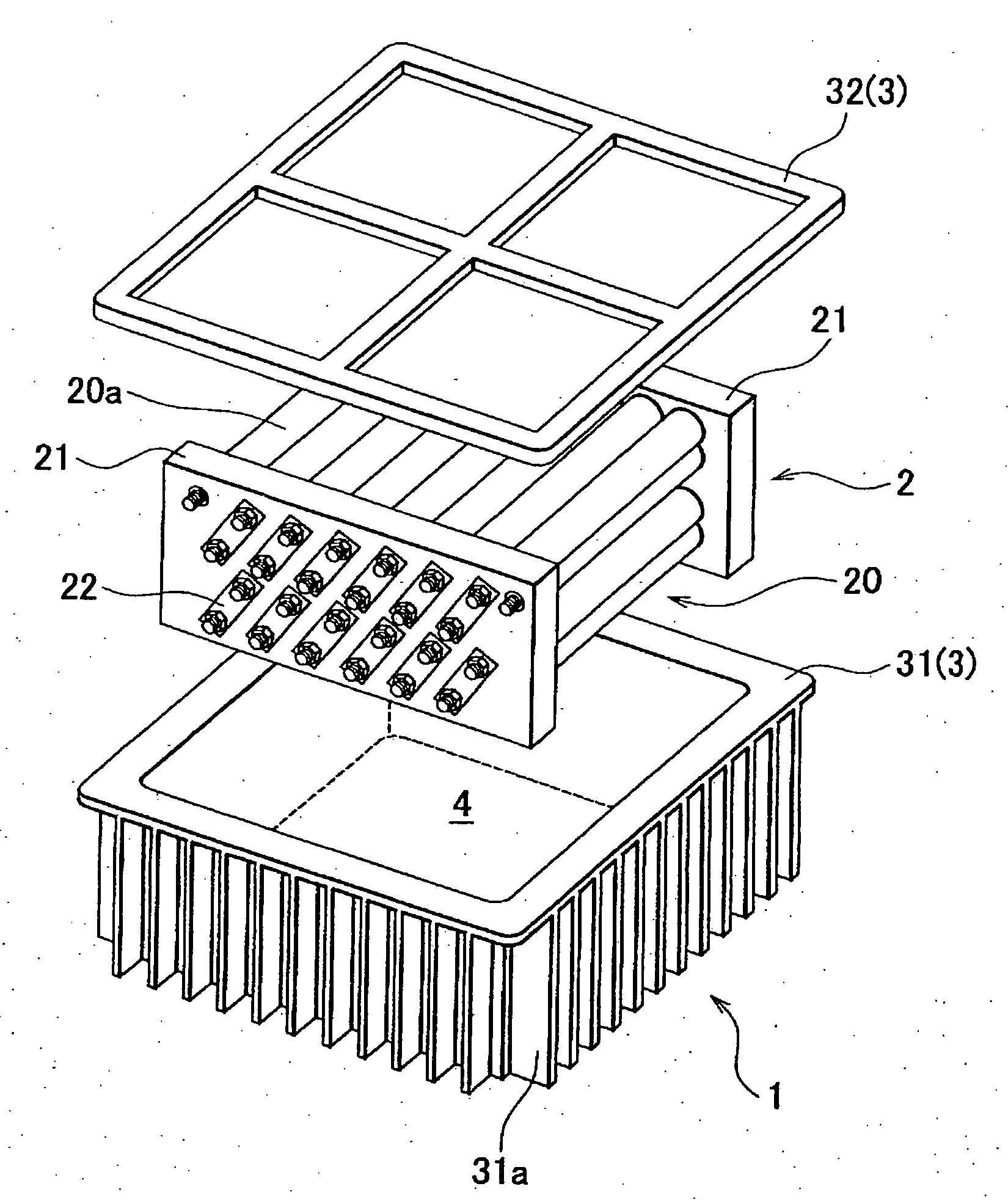
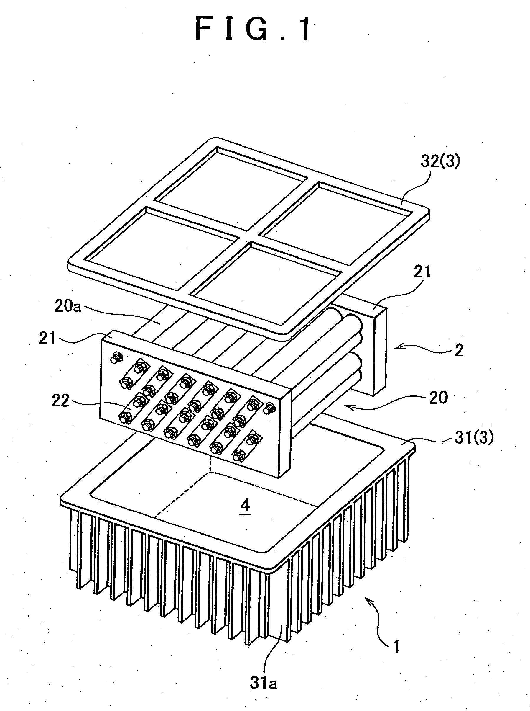
[0020]The structure of a battery pack 1 (power storage unit) according to the first example embodiment of the invention will be described with reference to FIG. 1. FIG. 1 is an exploded perspective view of the battery pack 1. The battery pack 1 is mounted in a vehicle.

[0021]The battery pack 1 is constituted of a pack case 3 (“case”), a power storage assembly 2 stored in the pack case 3, and coolant 4.

[0022]The pack case 3 is constituted of a case member 31 defining a space for storing the power storage assembly 2 and the coolant 4 and a lid member 32. The lid member 32 is fixed on the case member 31 using fasteners, such as bolts (not shown in the drawings), or by welding, or the like, whereby the inside of the pack case 3 is hermitically sealed

[0023]The case member 31 is fixed to a vehicle body member (not shown in the drawings) using fasteners, such as bolts, (not shown in the drawings), or by welding, or the like. Thus, the bottom face of the pack case 3 is in contact with the su...


PUM

PropertyMeasurementUnit
pressureaaaaaaaaaa
gravityaaaaaaaaaa
shapeaaaaaaaaaa

Abstract

A power storage unit has: a plurality of power storage modules each constituted of a power generation element and a power-generation-element-case containing the power generation element and disposed adjacent to each other, and a case containing the power storage modules and an insulative fluid. At least one groove is formed at the power-generation-element-case of each power storage module such that the power-generation-element-case breaks at the groove in response to an excessive increase in the pressure in the power-generation-element-case. The groove is formed in a portion of the power-generation-element-case that does not face any other power storage module.

Description

INCORPORATION BY REFERENCE[0001]The disclosure of Japanese Patent Application No. 2007-162601 filed on Jun. 20, 2007 including the specification, drawings and abstract is incorporated herein by reference in its entirety.BACKGROUND OF THE INVENTION[0002]1. Field of the Invention[0003]The invention relates to a power storage unit having a plurality of power storage modules each constituted of a power generation element and a case containing the power generation element and having at least one groove at its wall.[0004]2. Description of the Related Art[0005]In a secondary battery constituted of a power generation element and a case containing the power generation element, gas is produced from the power generation element due to excessive charging, and so on, and such gas increases the internal pressure of the case excessively.[0006]Japanese Utility Model Application Publication No. 06-21172 (JP-Y-06-21172) (e.g., FIG. 1) discloses a secondary battery having a case on which a groove is f...

Claims


Application Information

Patent Timeline
Patent Type & Authority Applications(United States)
IPC IPC(8): H01M2/10H01M6/42H01M50/213H01M50/242
CPCH01M2/1072H01M2/1241H01M10/625H01M10/6551H01M10/6567H01M10/643H01M10/613Y02E60/10H01M50/3425H01M50/213H01M50/242
Inventor NAKAMURA, YOSHIYUKI
Owner TOYOTA JIDOSHA KK
Why Eureka
Try Eureka