
Magnetic resonance system and method for correction of movement artifacts

Inactive Publication Date: 2008-12-25
SIEMENS HEATHCARE GMBH
View PDF6 Cites 30 Cited by
  • Summary
  • Abstract
  • Description
  • Claims
  • Application Information

AI Technical Summary

Benefits of technology

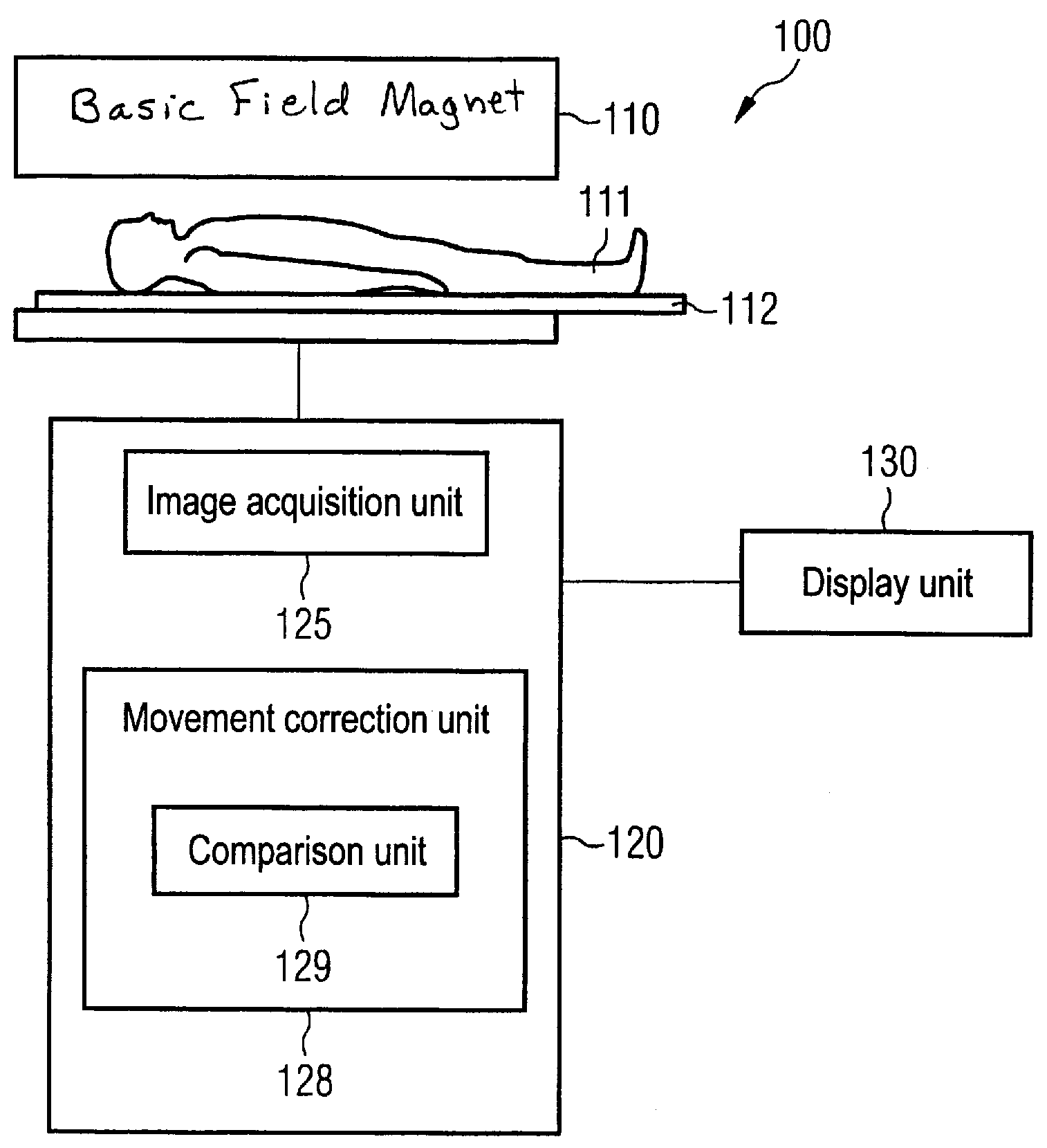
[0008]It is an object of the present invention to provide a method and an MR system in which inter-slice movements can be corrected.

Problems solved by technology

In imaging by means of magnetic resonance, movement of the examination subject during the signal acquisition typically leads to artifacts in the image that are more or less noticeable in a disruptive manner in the interpretation of the MR images.
For example, movement in the acquisition of a single slice leads to signal loss, signal smearing in the image, or to what are known as ghost artifacts.
Since the physician who “leafs through” the images normally examines the images in anatomical order given exposures in multiple slices, a translationally offset slice or a slice rotated by an angle is very disruptive for the assessing physician.
Each RF excitation pulse thus unavoidably also influences the slices adjacent to the excited slice.
In both acquisition techniques, however, the time span that elapses between the acquisition of adjacent slices is not negligible.
Such intra-slice movement corrections, however, cannot be used for correction of movement artifacts that result from movement between the acquisition / excitation of various anatomical slices.

Method used


Image

  • Magnetic resonance system and method for correction of movement artifacts
  • Magnetic resonance system and method for correction of movement artifacts
  • Magnetic resonance system and method for correction of movement artifacts

Examples


Embodiment Construction

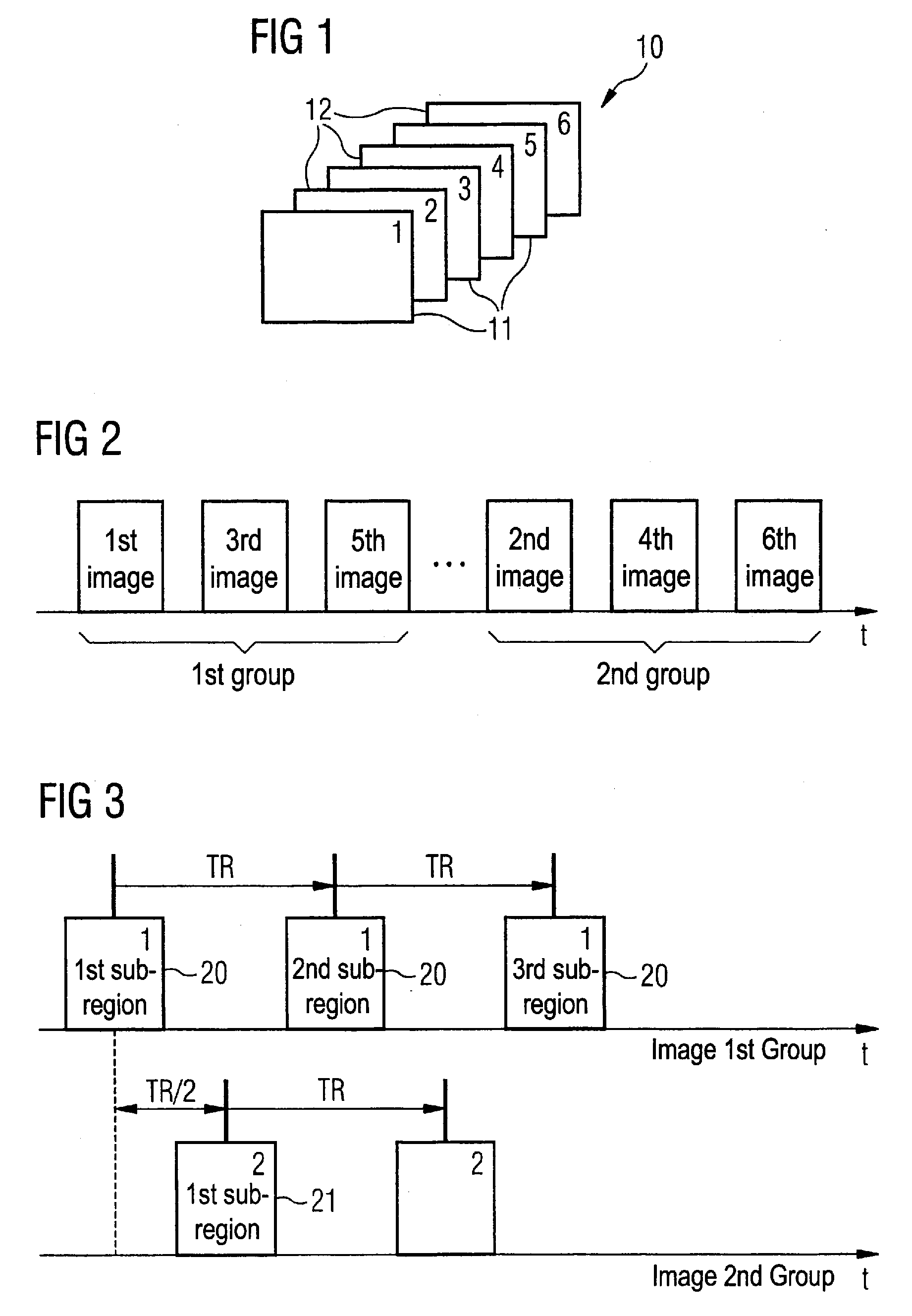
[0027]Various MR images are schematically shown in FIG. 1. Various slices 10 are acquired from an examination region (not shown), wherein the various slices 10 present the examination region in successive anatomical order. In one embodiment of the invention, the slices 10 are not acquired in succession dependent on their spatial position, rather the slices are divided into two different groups; for example, the slices of the first group 11 and the slices of the second group 12 exist. As mentioned above, for many application cases it is advantageous not to measure directly adjacent slices in direct succession, since an excitation of nuclear spins in the adjacent slice cannot be entirely precluded given the excitation of the nuclear spins in a slice. For this reason, for example, the slices of the first group (i.e. in the shown example the slices one, three and five) are measured and the slices of the second group (the slices two, four and six in the shown example) are measured at a l...


PUM


Abstract

In a method and magnetic resonance (MR) for correction of movement in the acquisition of MR images of an examination region, wherein the movement that occurs between the acquisition of data of spatially different slices of the examination region is taken into account, data from the examination region are acquired in multiple slices that are acquired in at least two groups, with slices of a second group arranged at least partially between slices of the first group, such that at least one slice of the second group lies between slices of the first group. Correction for movement of the examination region that occurred between the acquisition of data of the slices of the first group and the acquisition of data of an intervening slice of the second group is done by reconstructing a reference data set for the intervening slice from acquired slice data of the first group for the movement correction. This reference data set is compared with data of the acquisition of the MR image of the intervening slice in order to determine and correct the occurred movement.

Description

BACKGROUND OF THE INVENTION[0001]1. Field of the Invention[0002]The present invention concerns a method for correction of movement in the acquisition of MR (magnetic resonance) images and an MR system for this. The invention can in particular (but not exclusively) be used in the acquisition of MR images of the head. The invention can be applied in any other body region that is intrinsically rigid but is possibly subject to a translation or rotation movement.[0003]2. Description of the Prior Art[0004]In imaging by means of magnetic resonance, movement of the examination subject during the signal acquisition typically leads to artifacts in the image that are more or less noticeable in a disruptive manner in the interpretation of the MR images. Such movement artifacts can include artifacts due to movement of the examination subject that result in the acquisition of a single MR image (i.e. one slice). This is subsequently classified as an intra-slice movement that results given the acqu...

Claims


Application Information

Patent Timeline
IPC IPC(8): G06K9/00
CPCG01R33/56509G01R33/5676
Inventor STEMMER, ALTO
Owner SIEMENS HEATHCARE GMBH
Learn More