
Method and system for pulse frequency modulated switching mode power supplies

a technology of switching mode power supply and pulse frequency modulation, which is applied in pulse manipulation, pulse technique, instruments, etc., can solve the problems of large power supply transition power loss, and achieve the effect of reducing the power transistor's turn on transition loss

Active Publication Date: 2008-12-18
BCD SHANGHAI MICRO ELECTRONICS CO LTD
View PDF37 Cites 60 Cited by
  • Summary
  • Abstract
  • Description
  • Claims
  • Application Information

AI Technical Summary

Benefits of technology

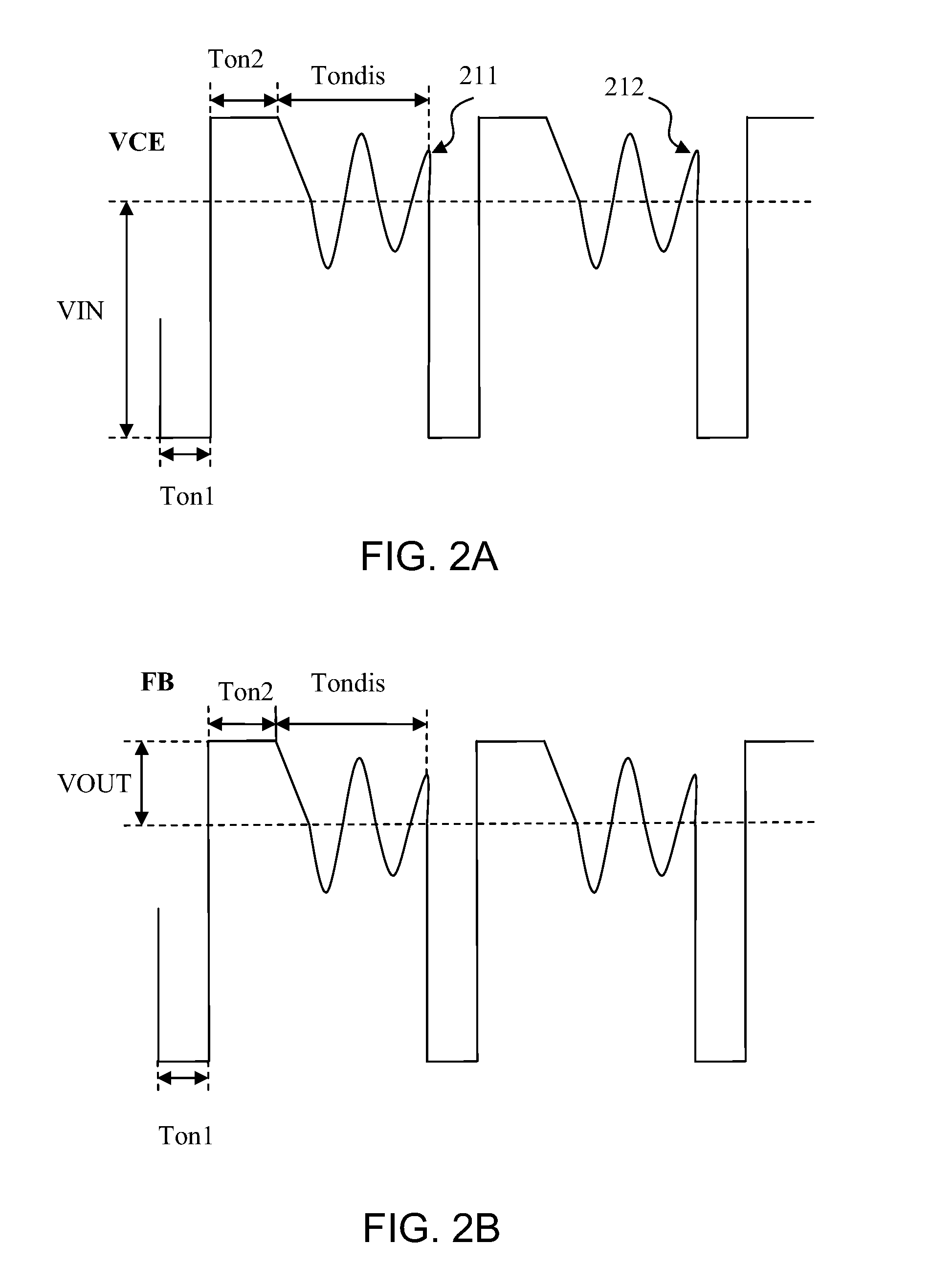
The present invention provides a method and system for controlling a power supply using PFM (Pulse Frequency Modulation) control. The invention includes a PFM controller that reduces power transistor's turn-on transition loss and introduces random dithering in the switching frequency spectrum. The PFM controller uses an oscillator to determine the timing of control signals, which advantageously reduces the power transistor's turn-on transition loss and introduces random dithering in the switching frequency spectrum. The PFM controller also includes a driver circuit, a feedback circuit, and a control circuit to provide the control signal. The invention provides a technique to force the power transistor to turn on at a valley of the resonant voltage ringing waveform, which reduces power loss and introduces random dithering in the switching frequency spectrum. The invention also includes a method for reducing power loss in a switching mode power supply by controlling the timing of the control signals.

Problems solved by technology

If the next control pulse is turned on at a peak of the ringing waveform, a large transition power loss can occur in the power supply.

Method used


Image

  • Method and system for pulse frequency modulated switching mode power supplies
  • Method and system for pulse frequency modulated switching mode power supplies
  • Method and system for pulse frequency modulated switching mode power supplies

Examples


Embodiment Construction

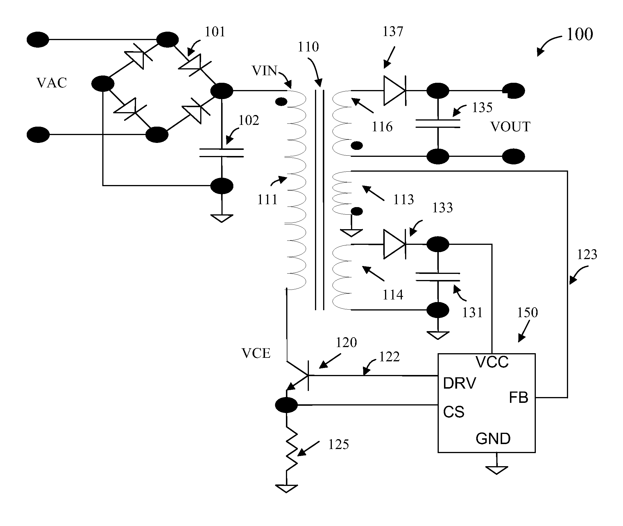
[0034]FIG. 1 is a simplified diagram illustrating a pulse frequency modulation (PFM) controlled switching mode power supply system 100 according to an embodiment of the present invention. This diagram is merely an example, which should not unduly limit the scope of the claims herein. One of ordinary skill in the art would recognize other variations, modifications, and alternatives. As shown, switching mode power supply 100 includes a power source VIN. Depending upon the embodiment, power source VIN can be derived from various power supplies. In the example shown in FIG. 1, VIN is a rectified DC power source derived from AC power source VAC through a rectifier circuit including bridge 101 and capacitor 102. Power supply 100 includes a transformer 110, which includes coil 111 as its primary winding. An output circuit of the power supply provides a regulated output voltage VOUT. As shown, the output circuit includes secondary winding coil 116, diode 137, and capacitor 135.

[0035]As show...


PUM


Abstract

A pulse frequency modulation (PFM) controller for controlling a switching mode power supply. The controller includes an output terminal for providing a control signal to turn on and off a current in the power supply to regulate an output of the power supply. A first input terminal receives a feedback signal related to the output of the power supply, the feedback signal exhibiting a ringing waveform when the current in the power supply is turned off. The controller also includes a control circuit configured to provide the control signal in response to the feedback signal. The control signal is adapted to turn on the current in the power supply when the feedback signal is substantially at a valley of the ringing waveform of the feedback signal. In an embodiment, such a PFM controller can reduce turn-on transition loss in a power supply and provides frequency dithering to reduce electromagnetic interference.

Description

CROSS-REFERENCES TO RELATED APPLICATIONS[0001]This application claims priority to U.S. Provisional Patent Application No. 60 / 943,498, filed Jun. 12, 2007, entitled “Method and system for Pulse Frequency Modulated Switching Mode Power Supplies” by inventors YaJiang Zhu et al., commonly assigned and incorporated by reference herein for all purposes.BACKGROUND OF THE INVENTION[0002]The present invention is directed to power supply control circuits. More particularly, the invention provides a method and system for Pulse Frequency Modulation (PFM) controller for controlling a switching mode power supply.[0003]Regulated power supplies are indispensable in modern electronics. For example, the power supply in a personal computer often needs to receive power input from various outlets. Desktop and laptop computers often have regulated power supplies on the motherboard to supply power to the CPU, memories, and periphery circuitry. Regulated power supplies are also used in a wide variety of ap...

Claims


Application Information

Patent Timeline
Patent Type & Authority Applications(United States)
IPC IPC(8): H02M3/335H03K12/00
CPCH02M1/44H02M3/33523H03K17/16H03K7/06H03K5/1532
Inventor ZHU, YAJIANGPENG, TAOFEI, RUIXIAFANG, SHAOHUA
Owner BCD SHANGHAI MICRO ELECTRONICS CO LTD
Learn More