Phase adjustment device and digital camera

Active Publication Date: 2008-12-18
PANASONIC SEMICON SOLUTIONS CO LTD
View PDF7 Cites 15 Cited by
  • Summary
  • Abstract
  • Description
  • Claims
  • Application Information

AI Technical Summary

Benefits of technology

[0011]Therefore, a main object of the present invention is to provide a phase adjustment device which is capable of a high-speed operation in the case where an optimal phase is changed due to environmental changes such as temperature change and which performs phase adjustment in real time while obtaining a moving image, whereby coping with such a recent trend as high speed of a driving pulse resulting from an increase in the number of pixels.

Problems solved by technology

The phases (timings) of these pulses cannot be easily adjusted in a hardware designing process due to some variability generated in a manufacturing process.
However, the imaging element cannot be easily exchanged in the case where an engineer has to readjust the phases.
In recent years, however, the pulse which drives the imaging element increases its speed as the number of the pixels in the imaging element is increased, which makes it difficult to optimally adjust the driving and detection pulses.
This recent trend created a new problem that a moving image cannot be obtained within a time range allowed for to perform the phase adjustment in a signal processing.
Without the conventional technology quoted earlier or the conventional technology recited in the disclosed Japanese Patent Document (No. 2005-151081 of the Japanese Patent Applications Laid-Open), it is difficult to perform the phase adjustment in real time while obtaining images.

Method used


Image

  • Phase adjustment device and digital camera
  • Phase adjustment device and digital camera
  • Phase adjustment device and digital camera

Examples


embodiment 1

Preferred Embodiment 1

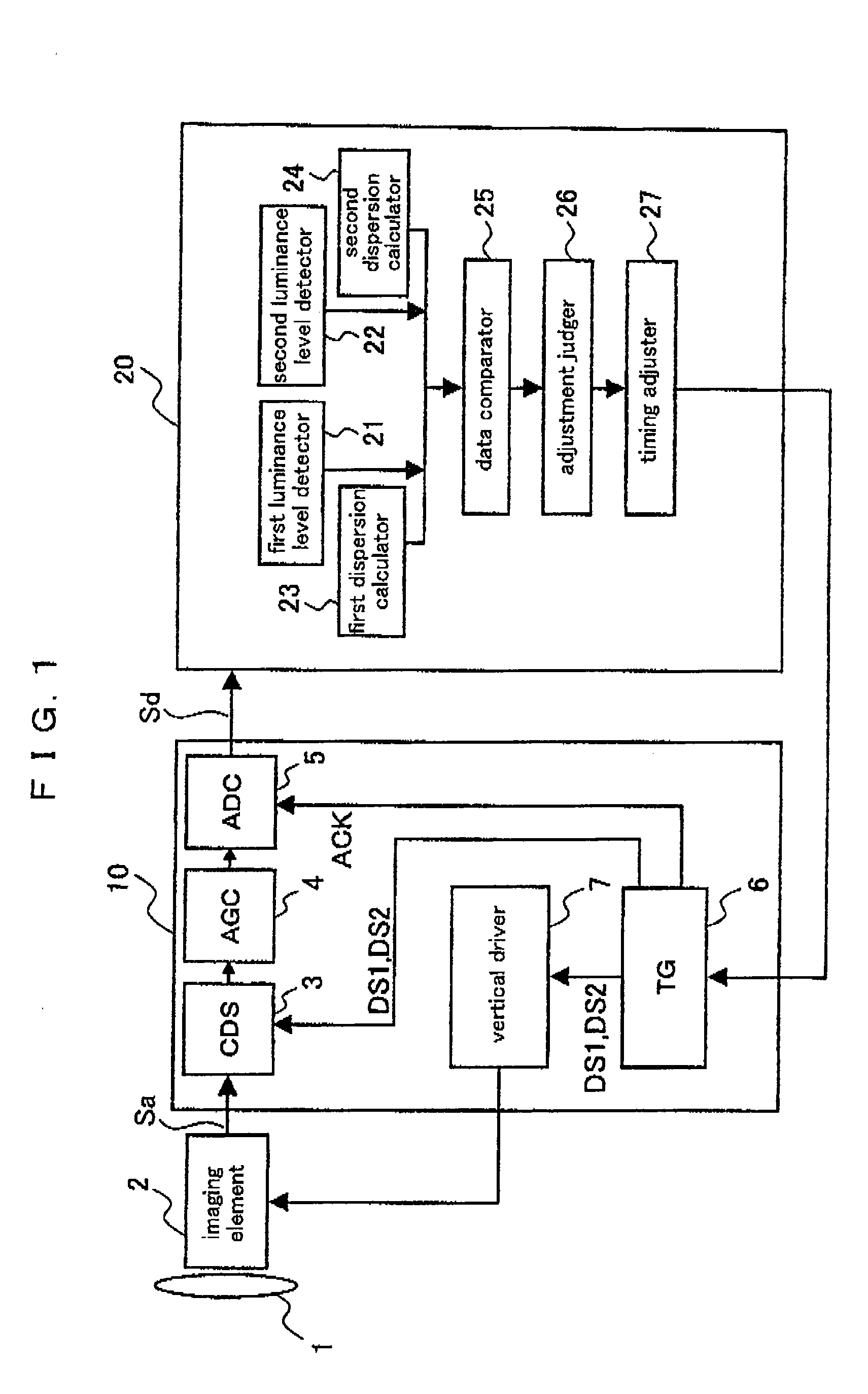
[0083]FIG. 1 is a block diagram illustrating an overall constitution of a digital camera according to a preferred embodiment 1 of the present invention. The digital camera according to the present preferred embodiment comprises an optical lens 1 for collecting light of a photographic subject on an imaging element, an imaging element 2 for obtaining an image of the photographic subject whose light is collected by the optical lens 1 (CCD is given as an example in the description below), an analog front end 10 providing predetermined processes to an imaging signal Sa (image data) outputted from the imaging element 2 and converting the processed signal into a digital imaging signal Sd, and a DSP (Digital Signal Processor) 20 for generating a video signal after providing predetermined processes (color correction, YC processing and the like) to the digital imaging signal Sd outputted from the analog front end 10.

[0084]The analog front end 20 comprises a correlated do...

embodiment 2

Preferred Embodiment 2

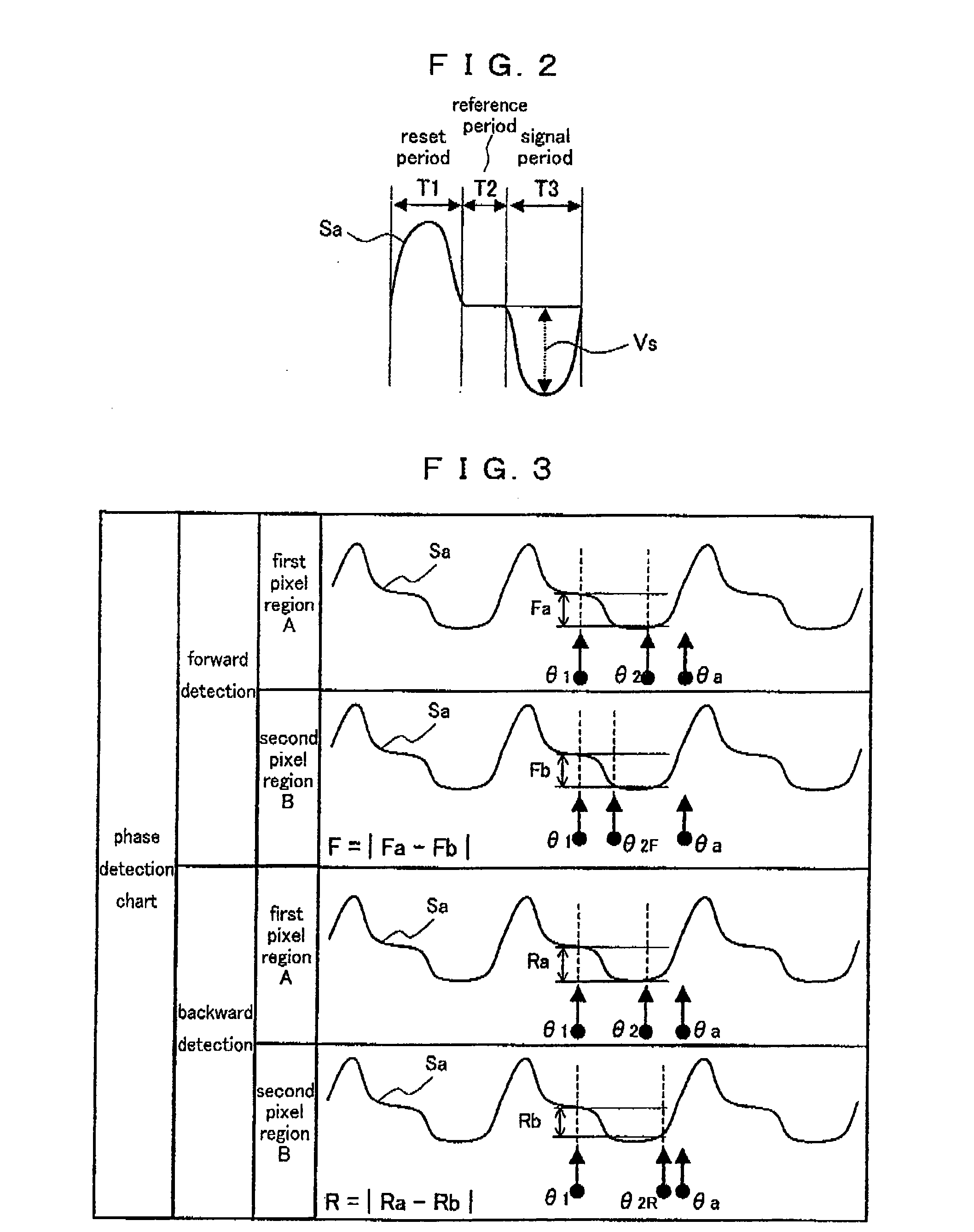
[0124]FIG. 8A is a flow chart of phase adjustment operations in a phase adjustment device according to a preferred embodiment 2 of the present invention. FIG. 8B is a condition table used in a phase changing method. These drawings correspond to FIGS. 7A and 7B according to the preferred embodiment 1. In the preferred embodiment 1, the luminance level difference between the first and second pixel regions A and B itself is used for the detection of the phase shift. In the present preferred embodiment, a ratio of the foregoing luminance level difference relative to the luminance level in the first pixel region A is used. Below is given a description. Steps S21 and S22 according to the present preferred embodiment are the same as the Steps S11 and S12 according to the preferred embodiment 1 (FIG. 7A). Therefore, the description thereof is omitted.

[0125]In Step S23, luminance level ratios Ratio F in the forward detection and Ratio R in the backward detection are cal...

embodiment 3

Preferred Embodiment 3

[0137]In the preferred embodiments 1 and 2, the phase shift is detected based on the luminance level difference. In a preferred embodiment 3 of the present invention, not the luminance level but the dispersion of the luminance level is used. More specifically, in the forward detection, a difference between the dispersion in the first pixel region A obtained by the first dispersion calculator 23 and the dispersion in the second pixel region B obtained by the second dispersion calculator 24 is calculated. Further, a difference between the dispersion in the first pixel region A and the dispersion in the second pixel region B is similarly calculated in the backward detection as well. A result of the comparison of the dispersion difference in the forward detection to a dispersion difference threshold value and a result of the comparison of the dispersion difference in the backward detection to the dispersion difference threshold value are checked against a condition...


PUM


Abstract

In a phase adjustment device according to the present invention, a first luminance level detector detects a luminance level of a digital imaging signal in a first pixel region, a second luminance level detector detects a luminance level of the digital imaging signal in a second pixel region, a data comparator compares detection results by the first and second luminance level detectors, an adjustment judger judges if it is necessary to adjust a phase of a pulse based on a result of the comparison by the data comparator, a timing adjuster shifts the phase of the pulse in the second pixel region when the luminance levels are detected, and further, the timing adjuster adjusts the phase of the pulse when the judgment by the adjustment judger indicates that the phase adjustment is necessary.

Description

BACKGROUND OF THE INVENTION[0001]1. Field of the Invention[0002]The present invention relates to a phase adjustment device for adjusting a phase (timing) of a pulse used for obtaining an image in a digital camera and a digital camera provided with the phase adjustment device.[0003]2. Description of the Related Art[0004]A digital camera (digital still camera, digital video camera, mobile telephone provided with a camera and the like) is configured such that an analog imaging signal obtained by an imaging element such as CCD or an MOS sensor is converted into a digital imaging signal, and the converted digital imaging signal is subjected to predetermined processing and then recorded. In order to obtain an image of a photographic subject using the imaging element, a pulse for driving the imaging element and a pulse for detecting a signal level are necessary. The phases (timings) of these pulses cannot be easily adjusted in a hardware designing process due to some variability generated ...

Claims


Application Information

Patent Timeline
IPC IPC(8): H04N5/228H03L7/00H04N5/335H04N5/341H04N5/357H04N5/363H04N5/372H04N5/376H04N5/378H04N101/00
CPCH04N5/335H04N5/3765H04N25/00H04N25/745
Inventor NOTSU, TAKUMANAKAMURA, KENJI
Owner PANASONIC SEMICON SOLUTIONS CO LTD
Why Eureka
Try Eureka