
Aerial Lifting and Propulsion Device (ALPD)

a propulsion device and air technology, applied in aircrafts, vehicles, air-flow influencers, etc., can solve the problems of not being able to teach or incorporate the features of air vehicles in the existing methodologies

Inactive Publication Date: 2008-12-11
MACK GERALD L
View PDF10 Cites 5 Cited by
  • Summary
  • Abstract
  • Description
  • Claims
  • Application Information

AI Technical Summary

Benefits of technology

[0006]Lift achieved through linear movement of wings does not involve direct control of the airspace around the wing(s), or the body of the winged craft, to achieve lift, but instead, aircraft is generated by controlling air, airspace, and / or atmospheric pressure directly above each rotor on the rotary aircraft, and, like fix winged aircraft, through adjustments in the speed and pitch of each rotor. However, once air, airspace, and / or atmosphere, has been moved to the lower surface of the rotor blade(s), the air, air space, and / or atmosphere are not further controlled, and moves quickly to re-fill the area of reduced atmospheric pressure created above each rotor, that made lift possible.

Problems solved by technology

While a wide range of operational winged and rotary aircraft effectively generate lift through forward motion and the use of rotor blades, and others use thrust and lighter than air features, none of the existing methodologies teach or incorporate features of the air vehicle disclosed and claimed in this application for patent(s).

Method used


Image

  • Aerial Lifting and Propulsion Device (ALPD)
  • Aerial Lifting and Propulsion Device (ALPD)
  • Aerial Lifting and Propulsion Device (ALPD)

Examples


Embodiment Construction

[0025]On Mar. 8, 2006, through the Law Offices of Fleishner and Kim, L.L.P., Registration Number 38128, I filed a Provisional Patent on the invention for which I am now seeking a Non Provisional Utility Patent in this application for a patent. The details of the Provisional Patent are as follows: Provisional Application; Docket Number GLM-0001PR; Inventor / Applicant: Mack, Gerald L; Residence: Centreville, Va.; Date Filed: Mar. 8, 2006; and Title of Invention: Aerial Lifting and Propulsion Device (ALPD).

[0026]The first claim of this invention is that the atmospheric conditions that create lift in a winged or rotary aircraft can be created around a stationary object, body or wing, hereafter referred to as a wing, by changing the configuration of the wing to be lifted, and any attachments, so that the wing has an inner and outer circumference. This means the wing configuration must be changed from the traditional rectangular, triangular or other configuration to a wing configuration th...


PUM


Abstract

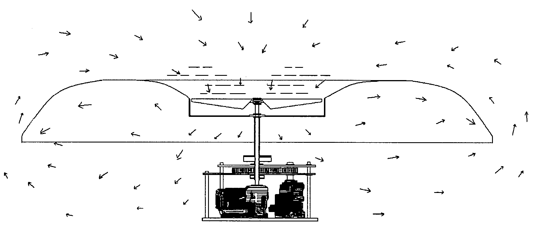
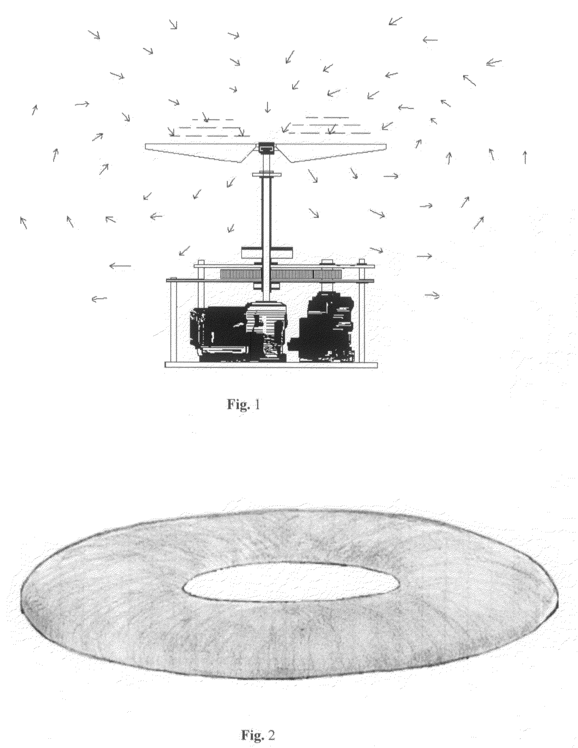
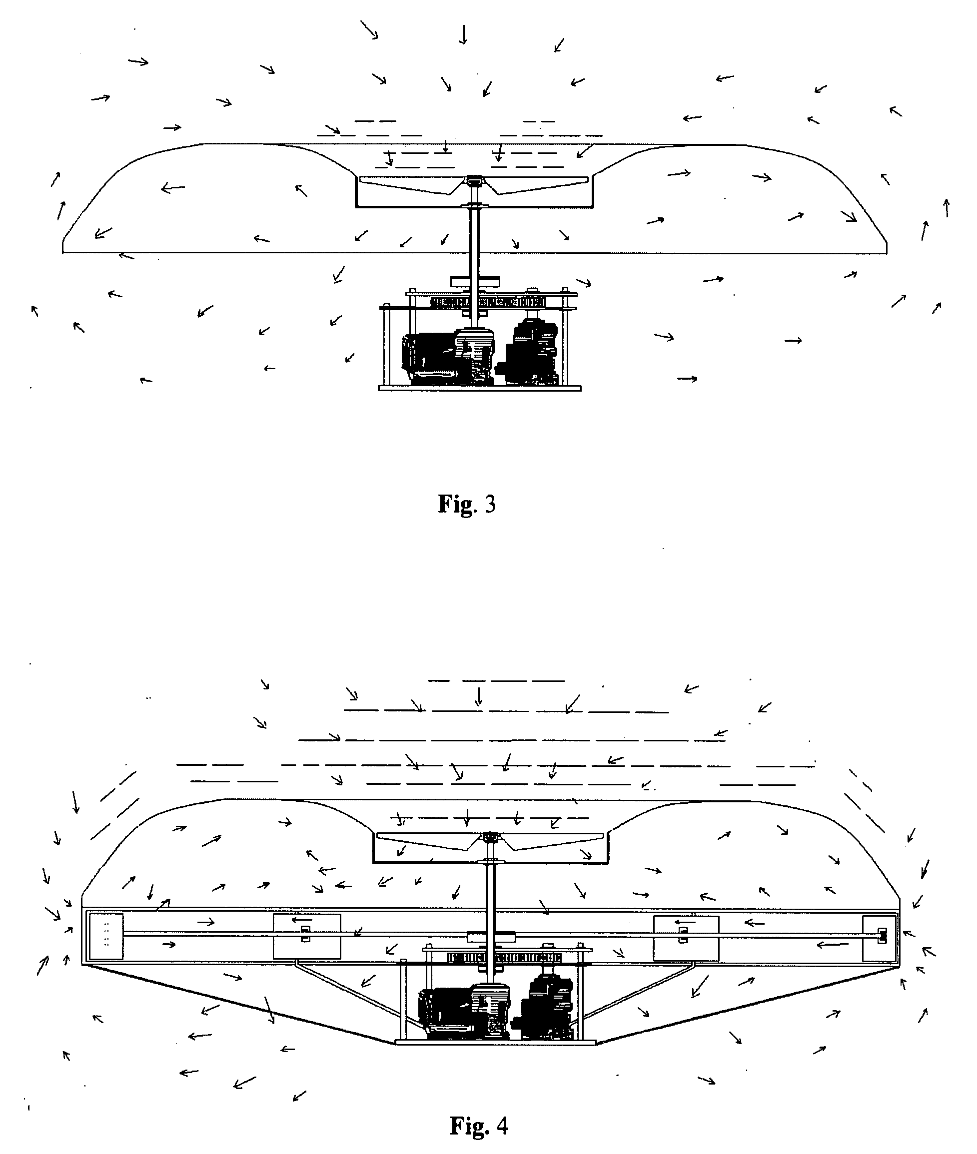
This invention, an Aerial Lifting and Propulsion Device, introduces an aircraft and aircraft wing design that has an outer and inner circumference, both of which are employed in the entirety of each to evacuate air, air space, and / or atmosphere from above the circular wing / craft, to the area beneath the circular wing / craft, through the use of a propeller inside the inner circumference of the circular wing, and impellers at the outer circumference of the circular wing. When the air, air space, and / or atmosphere forced from above the circular wing into the area beneath the circular wing and propeller attempts to escape to the top of the circular wing to fill the newly created low pressure area above the circular wing, it is intercepted at the lower edge of the outer circumference of the circular wing and forced to returned to the area beneath the circular wing, where the atmospheric pressure is further increased or decreased at will, depending on the pitch and speed of the aircraft propeller and impeller blades. The noted reduced atmospheric pressure at the top of the circular wing, and the higher controlled atmospheric pressure in the area beneath the circular wing and propeller, forces the circular wing upward from its stationary position, achieving lift as described in Bernoulli's Principle. Stabilization and directional control is maintained through adjustments in the pitch of the impeller and propeller and the effects of torque are neutralized by the rotation of the impeller and propeller assemblies in opposite directions. The Aerial Lifting and Propulsion Device maintains its upright configuration while airborne in part because its center of gravity is well below the points where lift is generated.

Description

STATEMENT REGARDING FEDERALLY SPONSORED RESEARCH OR DEVELOPMENT[0001]Not Applicable.REFERENCE TO SEQUENCE LISTING, A TABLE, OR A COMPUTER PROGRAM LISTING COMPACT DISK APPENDIX[0002]Not Applicable.BACKGROUND OF THE INVENTION[0003]This invention is an outgrowth of my research regarding concepts for creating lift from a stationary platform in a manner that is consistent with natural laws embodied in Bernoulli's Principle and certain of Newton's Laws. Presently, all aircraft rely on lift generated by the forward motion of wings or the rotational motion of propeller blades (similar to wings), except for rocket powered and lighter than air crafts. This invention provides a new means to mechanically create and control lift, from a stationary point, while exercising control of all air, airspace, and / or atmosphere that is in contact with the entire surface of the aircraft, including regulation of atmospheric pressure above and below the aircraft and its wing(s), at will, consistent with the ...

Claims


Application Information

Patent Timeline
IPC IPC(8): B64C39/00
CPCB64C39/064
Inventor MACK, GERALD L.
Owner MACK GERALD L
Learn More