Eureka AIR delivers breakthrough ideas for toughest innovation challenges, trusted by R&D personnel around the world.

Hose reel system

Inactive Publication Date: 2008-12-11
PUCK CUSTOM ENTERPRISES
View PDF15 Cites 4 Cited by
  • Summary
  • Abstract
  • Description
  • Claims
  • Application Information

AI Technical Summary

Benefits of technology

[0010]In an advantage provided by this invention, a hose reel system is provided which allows for pivoting of the hose reel to more efficiently wind the hose on a spool.
[0011]Advantageously, this invention provides a hose reel which is of a lightweight, low cost manufacture.
[0012]Advantageously, this invention provides a hose reel which is long lasting and easy to maintain.
[0013]Advantageously, this invention provides a hose reel which allows for more efficient winding of the hose at the ends of the spool.
[0014]Advantageously, this invention provides a hose reel which prevents the hose from winding beyond the ends of the spool.
[0015]Advantageously, in the preferred embodiment of this invention, a hose reel is provided which includes spool journaled to a frame along a first axis. A tongue is provided, pivotally coupled to a frame. A spool is journaled to the frame. An axle is coupled to the frame, and wheels are coupled to the axle. Means are provided for pivoting the tongue relative to the frame. In the preferred embodiment, the spool is provided with domed ends to more efficiently wind a hose near the ends of the spool, and an arch guard is provided to prevent the hose from winding beyond the ends of the spool.

Problems solved by technology

One drawback associated with the prior art is the tendency for the hose to wind on the spool in a single spot.
This causes overlapping and tangling of the hose, which can lead to twists, kinks and other malfunctions associated with the hose.
It can also lead to the hose tying up on itself as it winds on the spool.
When it is desired to unwind the hose from the spool, the hose may catch against itself and may cause tearing or ripping of the hose.
One drawback associated with prior art pivoting hose reels is that they simply turn back and forth.
While the back and forth motion tends to wind the hose somewhat more evenly along the spool, the turning is difficult to control and does not maximize the efficiency of the winding of the hose along the spool.
Another drawback associated with the prior art is the difficulty associated with winding the spool most efficiently at the ends of the spool.
As the ends of the spool are typically flat, it is difficult to obtain accurate winding at the end of the spool.
Still another drawback associated with the prior art is the tendency of the hose to extend beyond the edges of the spool during winding.
If this occurs, the hose can become entangled in the drive mechanism, causing damage to both the hose and the drive mechanism itself.

Method used


Image

  • Hose reel system
  • Hose reel system
  • Hose reel system

Examples


Embodiment Construction

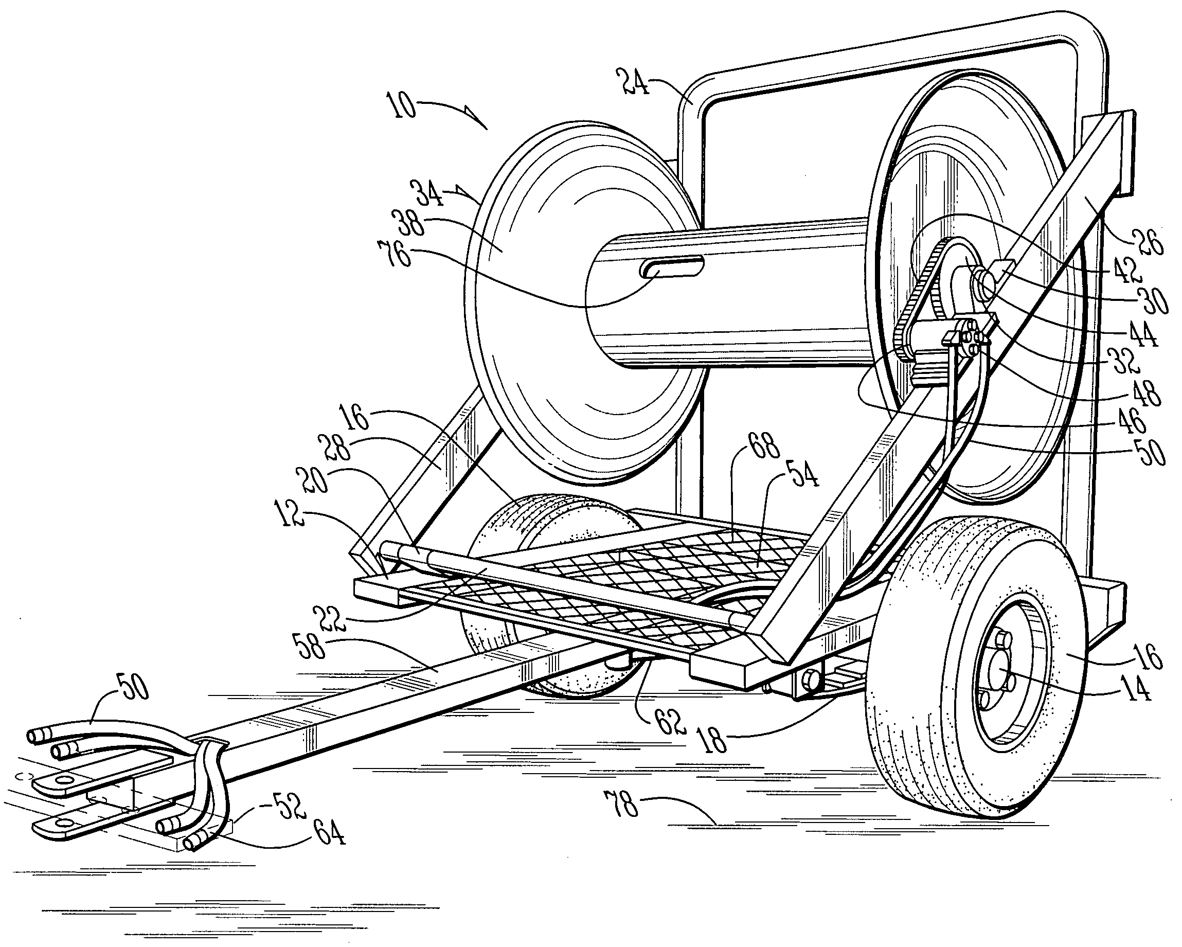
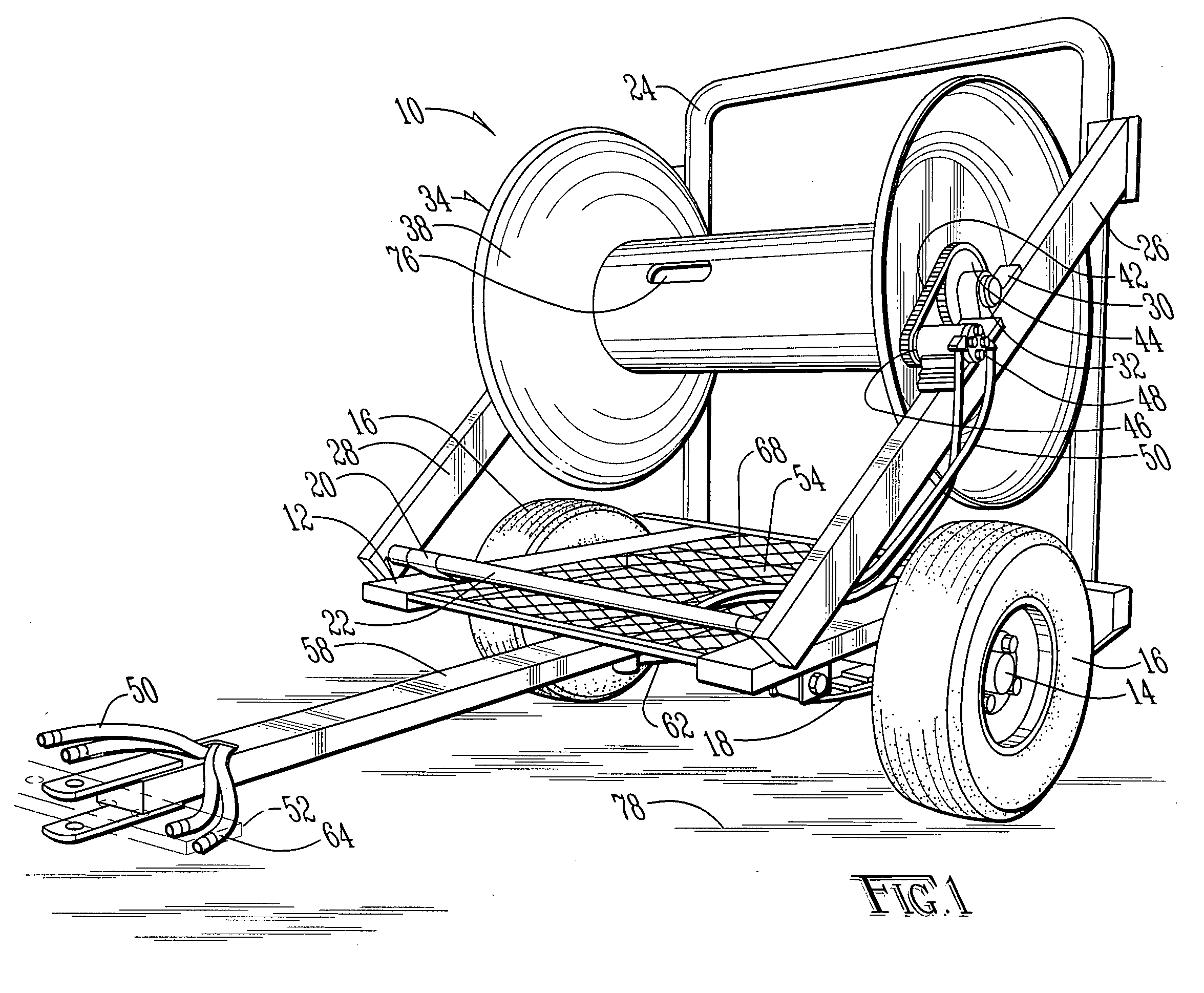
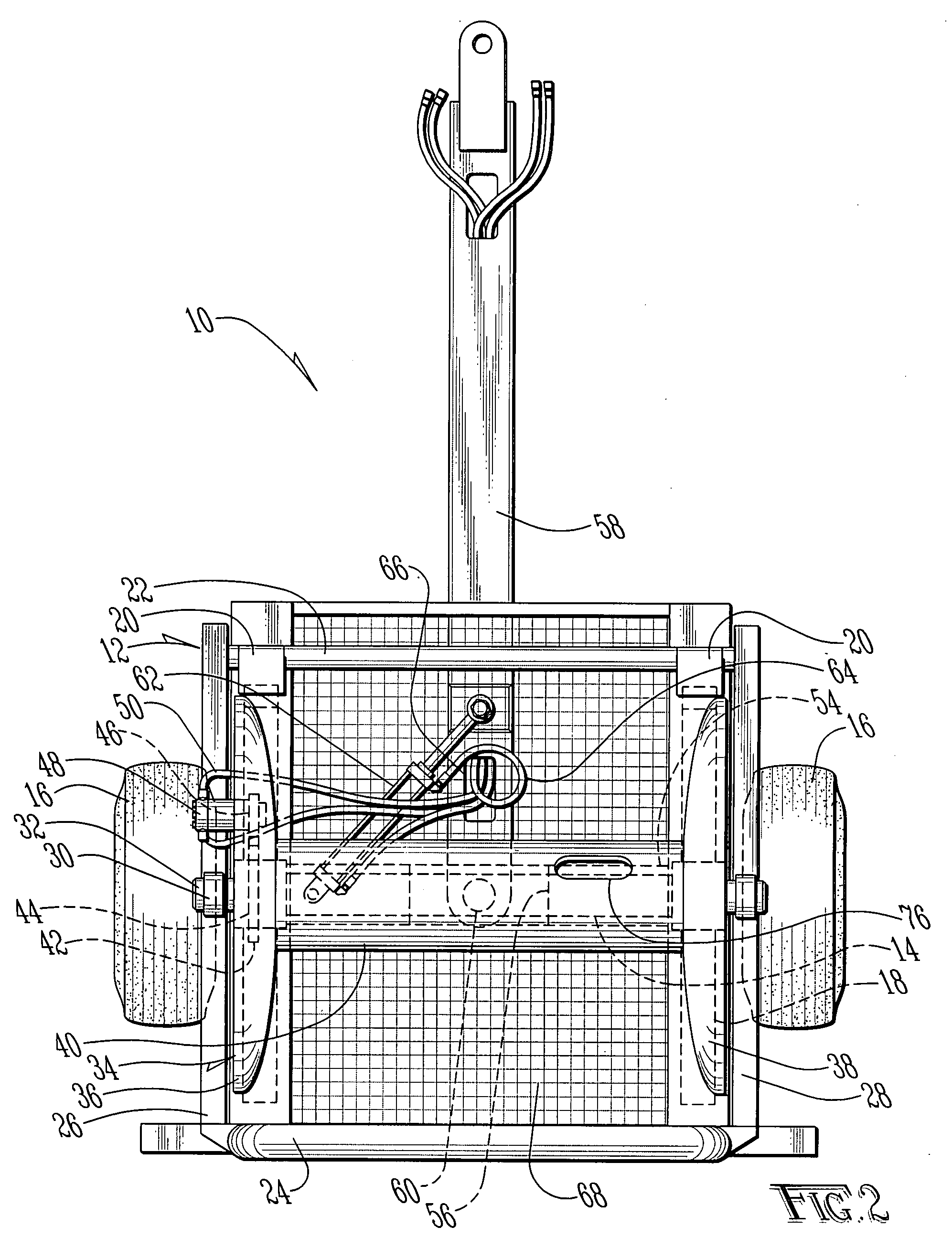
[0021]A hose reel according to the present invention is shown generally as (10) in FIG. 1. The hose reel (10) includes a frame (12). Journaled to the frame (12) is an axle (14) coupled to a pair of wheels (16). The axle (14) is coupled to the frame (12) by leaf springs (18), such as those known in the art.

[0022]Provided on the frame are a pair of support bars (20), supporting a shoulder (22). Coupled between the shoulder (22) and an arch guard (24) are a first angled support arm (26) and a second angled support arm (28). Provided on the angled support arms (26) and (28) are support brackets (30). Journaled between the support brackets (30) is an axle (32) around which is journaled a spool (34). The spool (34) includes a first curved dome (36) and a second curved dome (38), coupled to one another by a sleeve (40). Secured to the spool (34) is a large gear (42). The large gear (42) is coupled by a chain (44) to a small gear (46). As shown in FIG. 1, the small gear is driven by a hydra...


PUM


Abstract

A hose reel system for winding a liquid manure hose. The hose reel includes a spool pivoted in alignment with the wheels and axles of the system to allow for even winding of the hose on a spool. The spool is provided with curved domes on either, end and a protective bar to prevent the hose from winding beyond the ends of the spool. Pivoting the spool in alignment with the axle allows for a more even winding and unwinding of the hose, thereby reducing torsion, kinks and other damage to the hose during the rolling and unrolling processes.

Description

BACKGROUND OF THE INVENTION[0001]1. Field of the Invention[0002]The present invention relates in general to a hose reel system and, more particularly to a hose reel system for winding and unwinding a liquid manure hose on an agricultural field.[0003]2. Description of the Prior Art[0004]It is known in the art of agricultural liquid manure application to lay out a hose along the path of the manure application. A liquid manure supply and pump are connected to one end of the hose, and the manure applicator is connected to the other end. The manure applicator travels across the field delivering manure to the field for use as fertilizer. As it is desirable to quickly lay out and remove a hose from a field, it is known in the art to use hose reel systems which are pulled by a tractor or similar vehicle. Prior art hose reels typically include a large mechanically driven spool coupled to a wheeled frame. To lay out the hose, the hose is coupled at one end to a pump or similar stationary obje...

Claims


Application Information

Patent Timeline
IPC IPC(8): B65H75/48
CPCA01C23/008B65H75/425B65H75/4402B65H75/4489B65H2701/33
Inventor PUCK, BENNY D.
Owner PUCK CUSTOM ENTERPRISES
Why Eureka
Eureka Blog
Learn More