
Computer-controlled power wheelchair navigation system

a navigation system and computer control technology, applied in the field of wheelchair navigation system, can solve the problems of not being able to fully autonomously operate the known assistance device, the method has difficulty handling multiple and intersecting paths, and the known assistance device cannot be fully autonomous, so as to achieve the effect of enabling independent mobility for handicapped peopl

Inactive Publication Date: 2008-12-04
U S DEPT OF VETERANS AFFAIR +1
View PDF29 Cites 47 Cited by
  • Summary
  • Abstract
  • Description
  • Claims
  • Application Information

AI Technical Summary

Benefits of technology

[0012]An object of the present invention is to provide a navigation system that will enable independent mobility for handicapped people.

Problems solved by technology

These methods have difficulty handling multiple and intersecting paths, if they can handle them at all.
None of these known assistance devices are fully autonomous operations.
Moreover, none of these known assistance devices permit avoidance of wheelchair collision with obstacles during navigation of the wheelchair through a taught trajectory while allowing for close approach of the wheelchair to solid bodies present during performance of teaching functions.

Method used


Image

  • Computer-controlled power wheelchair navigation system
  • Computer-controlled power wheelchair navigation system
  • Computer-controlled power wheelchair navigation system

Examples


first embodiment

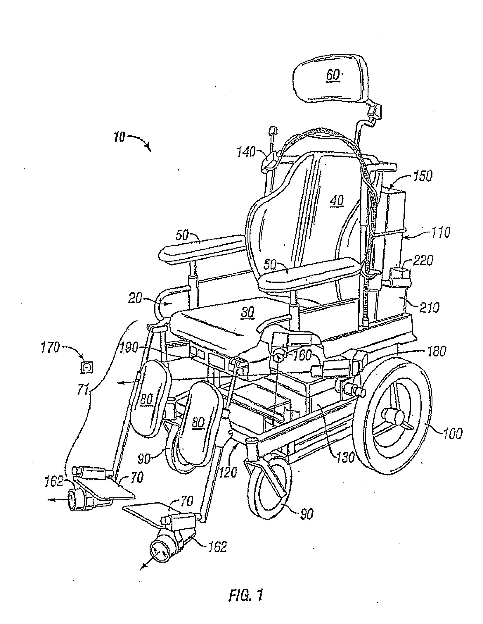
[0070]With the first embodiment, initial position estimates were either entered manually from the keyboard or were read from the first path file to be executed. This demanded exact placement of the wheelchair 20 at these coordinates prior to commencing travel, an inconvenient and potentially difficult task with a rider in the chair. Therefore, an additional software module can be used to estimate the wheelchair's initial position based on each camera's 160 ability to locate a unique configuration of cues 170. To enable autonomous navigation for the rider, the wheelchair 20 need only be placed anywhere in the vicinity of these cues 170 when the main software module is launched.

[0071]One of the first tasks of the locator module is to call the initialization routine in a loop. If either camera 160 cannot detect its initialization cues 170, the caregiver / attendant is notified accordingly by both a synthesized voice message and a message box (not shown). The message instructs the rider t...

second embodiment

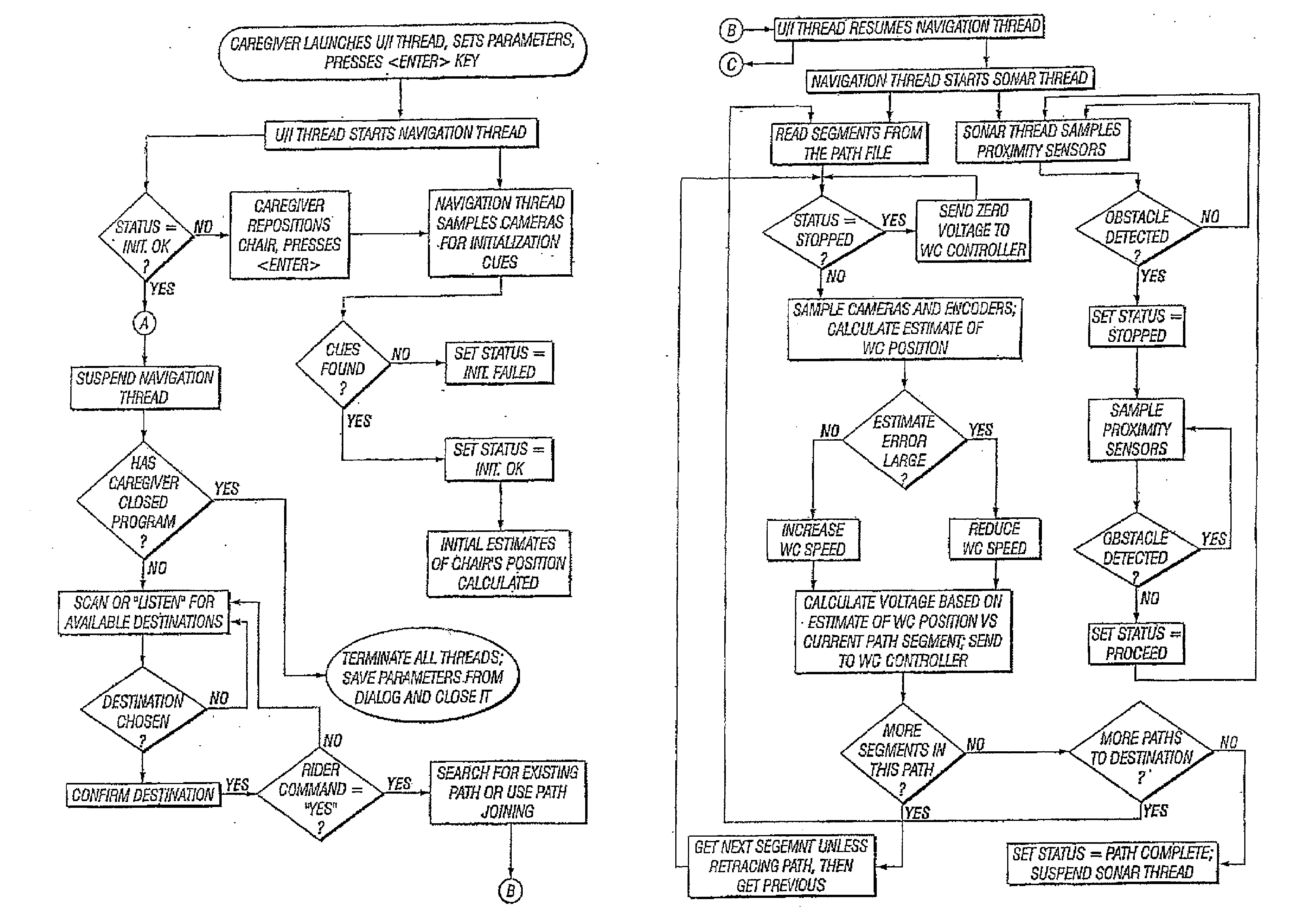
[0083]The second embodiment has a single computer 150. The main module has a user-interface (U / I) thread which, after all setup and initialization functions have been performed, the thread monitors the microphone or switch for user commands. Once the rider has selected and confirmed a destination for travel, the U / I thread initiates the navigation thread which, in turn, initiates the sonar thread for obstacle detection. During travel, the U / I thread continues to monitor the microphone or switch in the event the rider wishes to stop the wheelchair 20. When travel is completed, the navigation and sonar threads are suspended until the rider requests further travel. Under these circumstances, resources are consumed only as needed, ensuring maximum responsiveness of the user interface to the rider's actions. The threads communicate with each other by setting and reading a status variable. FIG. 6 represents a schematic chart of these parallel processes.

[0084]The navigation system 10 can n...


PUM


Abstract

A wheelchair navigation system for a motorized wheelchair includes dual cameras, proximity sensors, microphones, and rotation sensors for the wheels. Small markers are placed on the walls of a location or room. The navigation system uses the proximity sensors, rotation sensors and cameras in conjunction with the specialized software to determine where objects or impediments are located in the room and thereby redirect the path of the wheelchair so as to avoid such objects. The wheelchair is walked through the marked location thereby ‘teaching’ various paths which are recorded in the computer and recalled later when the wheelchair is in use. The proximity sensor perform sensing operations during performance of the teaching functions for thereby permitting avoidance of wheelchair collision with obstacles during navigation of the wheelchair through a taught trajectory and allowing for close approach of the wheelchair to solid bodies present during performance of the teaching functions.

Description

RELATED APPLICATIONS[0001]This application is a Continuation-in-Part of and claims benefit of priority of U.S. application Ser. No. 10 / 890,411, filed Jul. 14, 2004, which is a Continuation-in-part of and claims benefit of priority of U.S. application Ser. No. 10 / 187,989, filed Jul. 2, 2002, now U.S. Pat. No. 6,842,692, hereby incorporated by reference in their entiretyBACKGROUND OF INVENTION[0002]a. Field of Invention[0003]This invention relates to a wheelchair navigation system, and more particularly to a computer-controlled power wheelchair navigation system that allows a person to navigate through a location with pre-established paths, and with voice or manually activating the computer.[0004]b. Description of Related Art[0005]A significant population of severely disabled people require mobility assistance in daily living activities beyond what is available in conventional powered wheelchairs. The present invention is aimed at a segment of that population, those unable to manually...

Claims


Application Information

Patent Timeline
IPC IPC(8): A61G5/10G01C21/00
CPCA61G5/10G01C21/20A61G2203/22
Inventor FEHR, LINDASKAAR, STEVEN B.DEL CASTILLO, GUILLERMO
Owner U S DEPT OF VETERANS AFFAIR
Learn More