
Portable power and utility system

a portable, power and utility technology, applied in the field of portable power and utility equipment, to achieve the effect of improving the environment, low noise level, and minimal nois

Active Publication Date: 2008-12-04
WINDSOR MICHAEL E
View PDF2 Cites 51 Cited by
  • Summary
  • Abstract
  • Description
  • Claims
  • Application Information

AI Technical Summary

Benefits of technology

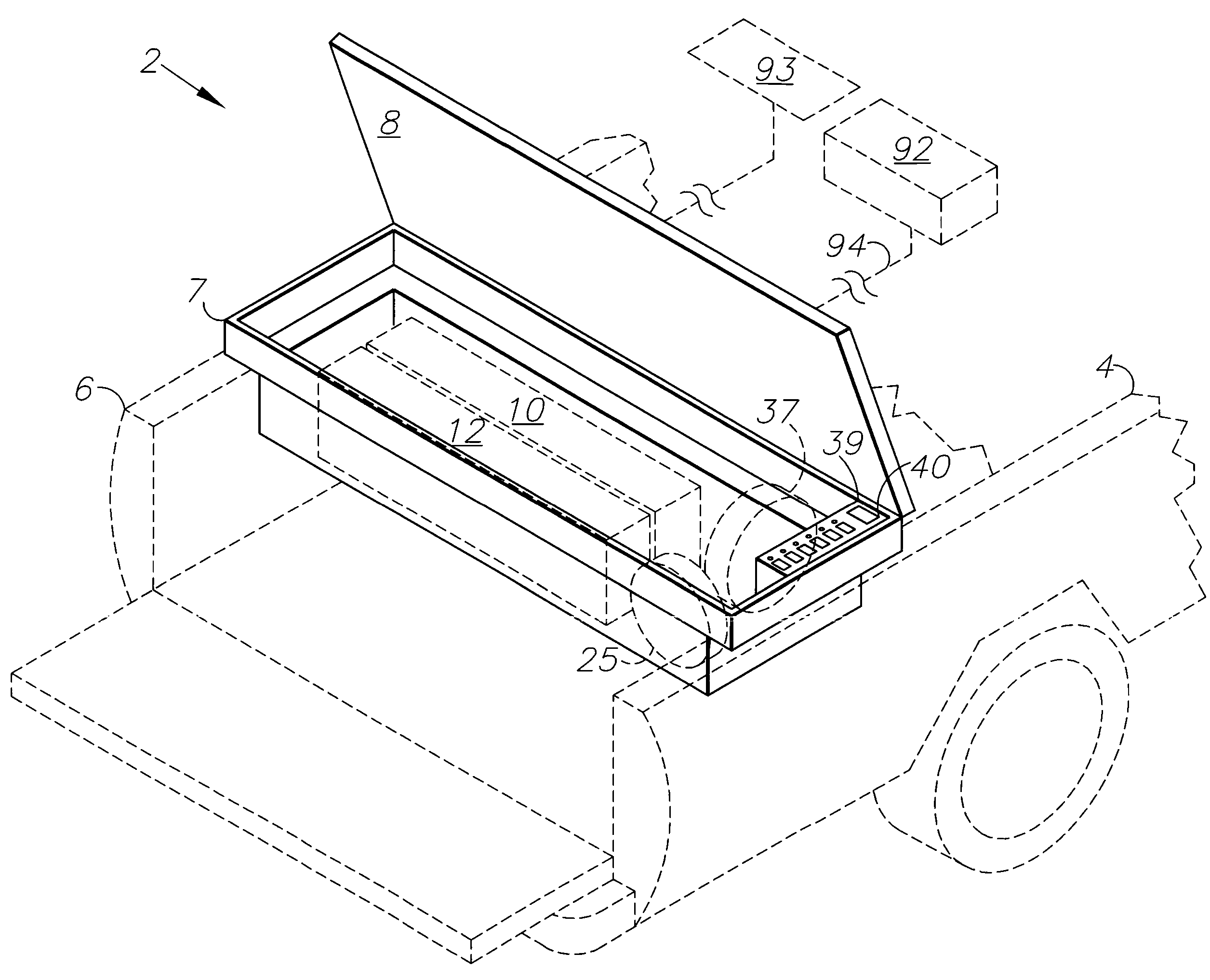
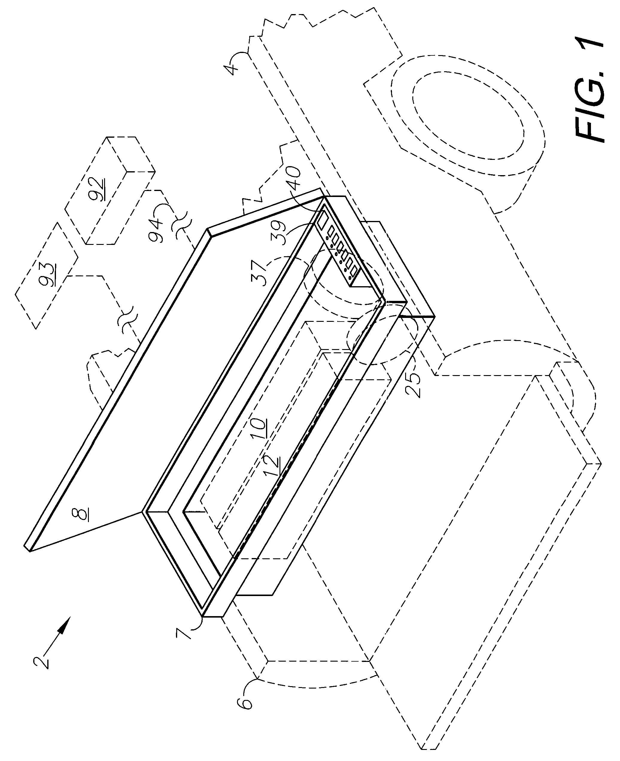
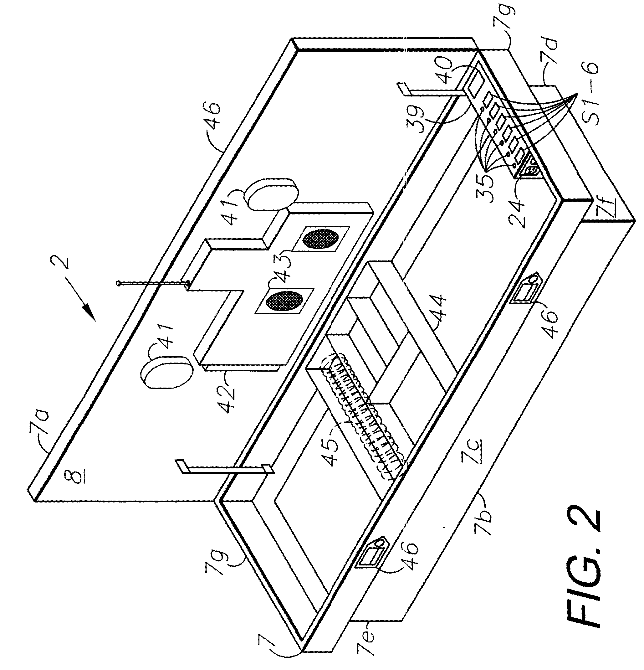
[0010]While providing power to the user, if the power and utility system battery should become depleted, the vehicle can simply be started and idled whereby the power and utility system automatically connects to the vehicle power system. In this configuration the power and utility system will draw power from the vehicle's power system and can continue to provide AC power to the home or other power load. When the power and utility system battery is recharged the vehicle motor can be turned off. The power and utility system does not need to be fully recharged to supply power, as long as the vehicle motor has operated long enough to build up a reserve capacity inside the power and utility system battery. The power and utility system itself is considered environmentally “green,” quiet, and safe, since the vehicle motor has a catalytic converter and must meet emissions standards. National parks and other overnight parking areas no longer allow generators and / or may have “no idle” rules for parked vehicles. The power and utility system can quietly supply hours of AC and / or DC power to the user as required, with no noise or fuel exhaust emission of any kind, thus, improving the environment and complying with the noise regulations of the areas. The pneumatic air pumps and hydraulic pumps make a low level noise while running, but as they are contained and built-in inside the enclosure, their noise level is minimal and noninvasive. The system can include an internal battery charger adapted for charging its own battery or various other external batteries and those of a host vehicle. Alternatively, the system can be configured for operating completely independently of a host vehicle or any other device or facility for hours at a time (depending on power draw requirements and capacity of the system).

Problems solved by technology

National parks and other overnight parking areas no longer allow generators and / or may have “no idle” rules for parked vehicles.

Method used


Image

  • Portable power and utility system
  • Portable power and utility system
  • Portable power and utility system

Examples


Embodiment Construction

I. Introduction and Environment

[0021]As required, detailed embodiments of the present invention are disclosed herein; however, it is to be understood that the disclosed embodiments are merely exemplary of the invention, which may be embodied in various forms. Therefore, specific structural and functional details disclosed herein are not to be interpreted as limiting, but merely as a basis for the claims and as a representative basis for teaching one skilled in the art to variously employ the present invention in virtually any appropriately detailed structure.

[0022]Certain terminology will be used in the following description for convenience in reference only and will not be limiting. For example, up, down, front, back, right and left refer to the invention as oriented in the view being referred to. The words “inwardly” and “outwardly” refer to directions toward and away from, respectively, the geometric center of the embodiment being described and designated parts thereof. Forwardly...


PUM


Abstract

A portable power and utility system for mounting in or on a host vehicle with an electrical system or, alternatively, operating in a standalone, portable configuration. The portable power and utility system includes an enclosure, an AC power subsystem mounted in the enclosure, a fluid power air subsystem mounted in the enclosure and an optional host vehicle connection adapted for selectively connecting the electrical system of the host vehicle and the AC power subsystem. A battery charger subsystem is connected to one or both of the host vehicle electrical system and the AC power subsystem. Wheels can be mounted on the enclosure for transportation. A control panel is mounted in the enclosure and includes multiple switches for controlling operation of the subsystems.

Description

CROSS REFERENCE TO RELATED APPLICATION[0001]This application claims priority in provisional application No. 60 / 941,866, filed Jun. 4, 2007, which is incorporated herein by reference.BACKGROUND OF THE INVENTION[0002]1. Field of the Invention[0003]The present invention relates generally to specialized power and utility equipment, and in particular to a compact, portable system for providing a broad range of power and utility functions in various environments, which can be remote from other sources of power such as alternating current (AC) electrical, direct current (DC) electrical, pneumatic, hydraulic, and other forms of power, for performing a broad range of tasks, including powering a variety of power tools, charging portable power tools and powering other equipment and other systems and assisting in various tasks.[0004]2. Description of the Related Art[0005]Various types of power and utility equipment and resources are used to operate power devices and to perform work operations. ...

Claims


Application Information

Patent Timeline
IPC IPC(8): H02J7/00H05K7/00H01M50/249H01M50/269
CPCH01M2/1072H02J2001/006H02J7/0029H01M10/46H02J1/122Y02E60/10H01M50/249H01M50/269
Inventor WINDSOR, MICHAEL E.
Owner WINDSOR MICHAEL E
Learn More