
Apparatus and methods for securing a first structural member and a second structural member to one another

a technology of structural members and securing devices, applied in the direction of couplings, rod connections, manufacturing tools, etc., can solve the problems of de-bonding and bonding failure, disadvantageous structural loading issues, and pi fittings

Active Publication Date: 2008-12-04
THE BOEING CO
View PDF19 Cites 31 Cited by
  • Summary
  • Abstract
  • Description
  • Claims
  • Application Information

AI Technical Summary

Benefits of technology

[0009]The preferred embodiments of the present apparatus and methods have several features, no single one of which is solely responsible for their desirable attributes. Without limiting the scope of these apparatus and methods as expressed by the claims that follow, their more prominent features will now be discussed briefly. After considering this discussion, and particularly after reading the section entitled “Detailed Description of the Preferred Embodiments”, one will understand how the features of the preferred embodiments provide advantages which include increased resistance to pull-off loads and impact loads, a relatively benign failure mechanism, allowance for thickness variations in the structural members, preservation of adhesive during installation, and reduced complexity in applying adhesive.

Problems solved by technology

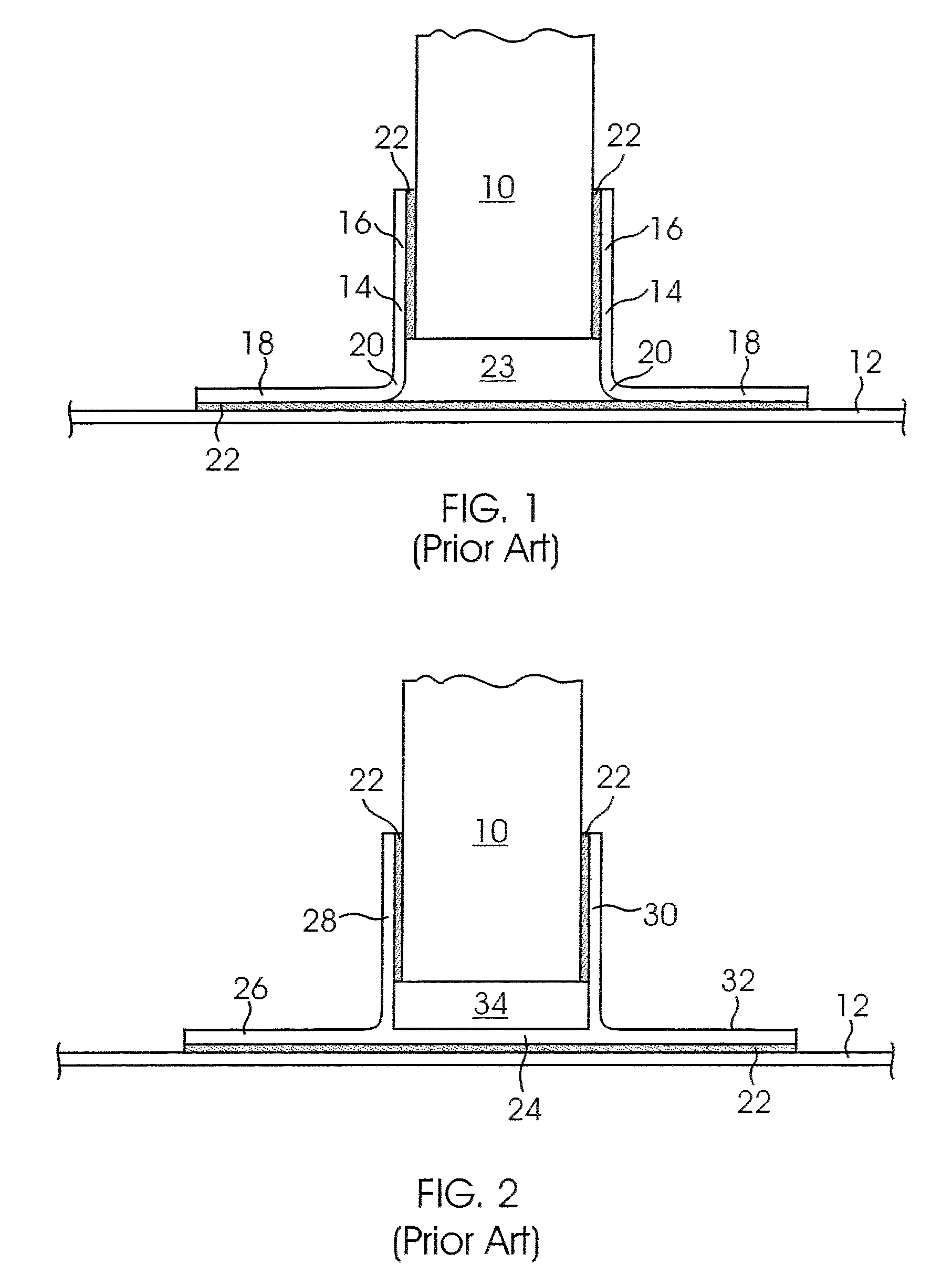
The method of attachment illustrated in FIG. 1 creates disadvantageous structural loading issues when pull-off loads are high.
Cracks can propagate through the resin to the angles 14 causing de-bonding and bond failure.
However, the Pi fitting 24 presents installation issues due to the fixed distance between the second and third sections 28, 30.

Method used


Image

  • Apparatus and methods for securing a first structural member and a second structural member to one another
  • Apparatus and methods for securing a first structural member and a second structural member to one another
  • Apparatus and methods for securing a first structural member and a second structural member to one another

Examples


Embodiment Construction

”, one will understand how the features of the preferred embodiments provide advantages which include increased resistance to pull-off loads and impact loads, a relatively benign failure mechanism, allowance for thickness variations in the structural members, preservation of adhesive during installation, and reduced complexity in applying adhesive.

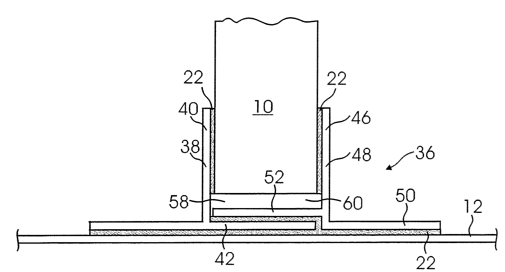
[0010]One embodiment of the present apparatus and methods comprises a fitting configured to secure a first structural member and a second structural member to one another. The fitting comprises a first piece including a first section and a second section. The first and second sections adjoin one another at a substantially perpendicular angle. The fitting further comprises a second piece including a third section, a fourth section and a fifth section. The third and fourth sections adjoin one another at a substantially perpendicular angle. The third and fifth sections adjoin one another at a substantially perpendicular angle. The fourth and ...


PUM

PropertyMeasurementUnit
perpendicular angleaaaaaaaaaa
attachment anglesaaaaaaaaaa
angleaaaaaaaaaa

Abstract

Apparatus and methods for securing a first structural member and a second structural member to one another. In one embodiment a two-piece fitting is provided. The fitting includes a variable gap between attachment surfaces, enabling the fitting to accommodate structural members of variable thickness. The fitting also includes overlapping sections that provide increased resistance to pull-off loads and impact loads. The configuration of the fitting advantageously simplifies the assembly process and preserves the integrity of the adhesive to form a strong joint.

Description

BACKGROUND[0001]1. Technical Field[0002]The present disclosure relates to apparatus and methods for securing a first structural member and a second structural member to one another.[0003]2. Description of Related Art[0004]FIG. 1 illustrates one common method for securing a first structural member 1I and a second structural member 12 to one another. The first structural member 10 may be, for example and without limitation, a frame, a bulkhead, a cap or a rib. The second structural member 12 may be, for example and without limitation, a wing skin, a floor panel or a fuselage skin panel. First and second attachment angles 14 secure the structural members 10, 12 to one another. Each angle 14 comprises a first section 16 and a second section 18. The sections 16, 18 may be substantially planar, or may include some curvature. For simplicity, the sections 16, 18 are illustrated herein as being planar.[0005]The sections 16, 18 are substantially perpendicular to one another and are joined at ...

Claims


Application Information

Patent Timeline
Patent Type & Authority Applications(United States)
IPC IPC(8): F16B1/00B21D53/92B64C1/00
CPCB64C1/06B64C1/12B64F5/0009Y10T403/64Y10T29/53Y10T29/49623Y10T29/49622Y10T403/34B64F5/10F16B2200/50
Inventor KULESHA, RICHARD L.
Owner THE BOEING CO
Learn More