
Image sensing apparatus and control method

a technology of image sensor and control method, which is applied in the direction of exposure control, instruments, television systems, etc., can solve the problems of misleading users, causing a portion of the image sensor to heat up and burn out, and users not being able to see the image of objects entering the image sensor

Inactive Publication Date: 2008-11-27
CANON KK
View PDF5 Cites 7 Cited by
  • Summary
  • Abstract
  • Description
  • Claims
  • Application Information

AI Technical Summary

Benefits of technology

[0009]The present invention has been made in consideration of the above situation, and has as its object to protect the image sensor and at the same time to enable return to a screen showing an image of an object more quickly when displaying an image other than an image of an object in an electronic viewfinder mode.

Problems solved by technology

However, because the menu screen is being displayed, the user cannot see the image of the object that is entering the image sensor.
As a result, for example, if the photographing lens is inadvertently pointed toward the sun, sunlight is then focused on the image sensor, possibly causing a portion of the image sensor to heat up and burn out.
If the mirror is moved every time there is a switch to the menu screen, the sound of the mirror moving, and especially the sound of impact as the mirror descends into place, not only is noisy but can also mislead the user into thinking that the shutter release button has been pressed.
In addition, when returning from display of the menu screen to the EVF display screen to once again display an image of the object, because the mirror has to be driven it takes longer to return to the screen showing the image of the object, which is inconvenient.

Method used


Image

  • Image sensing apparatus and control method
  • Image sensing apparatus and control method
  • Image sensing apparatus and control method

Examples


Embodiment Construction

[0026]A preferred embodiment of the present invention will be described in detail in accordance with the accompanying drawings. The dimensions, shapes and relative positions of the constituent parts shown in the embodiment should be changed as convenient depending on various conditions and on the structure of the apparatus adapted to the invention, and the invention is not limited to the embodiments described herein.

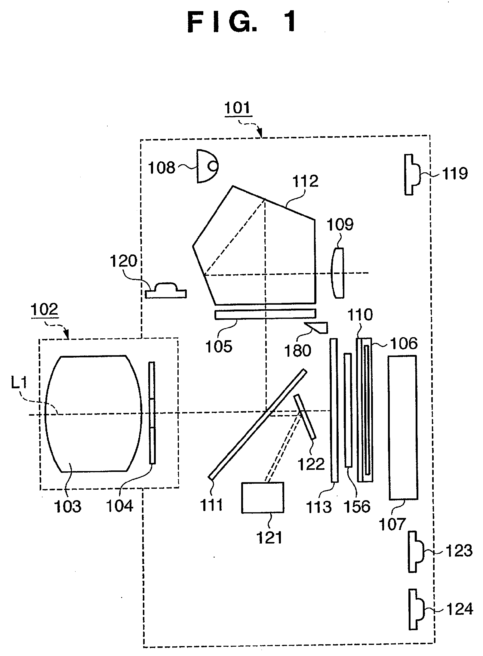
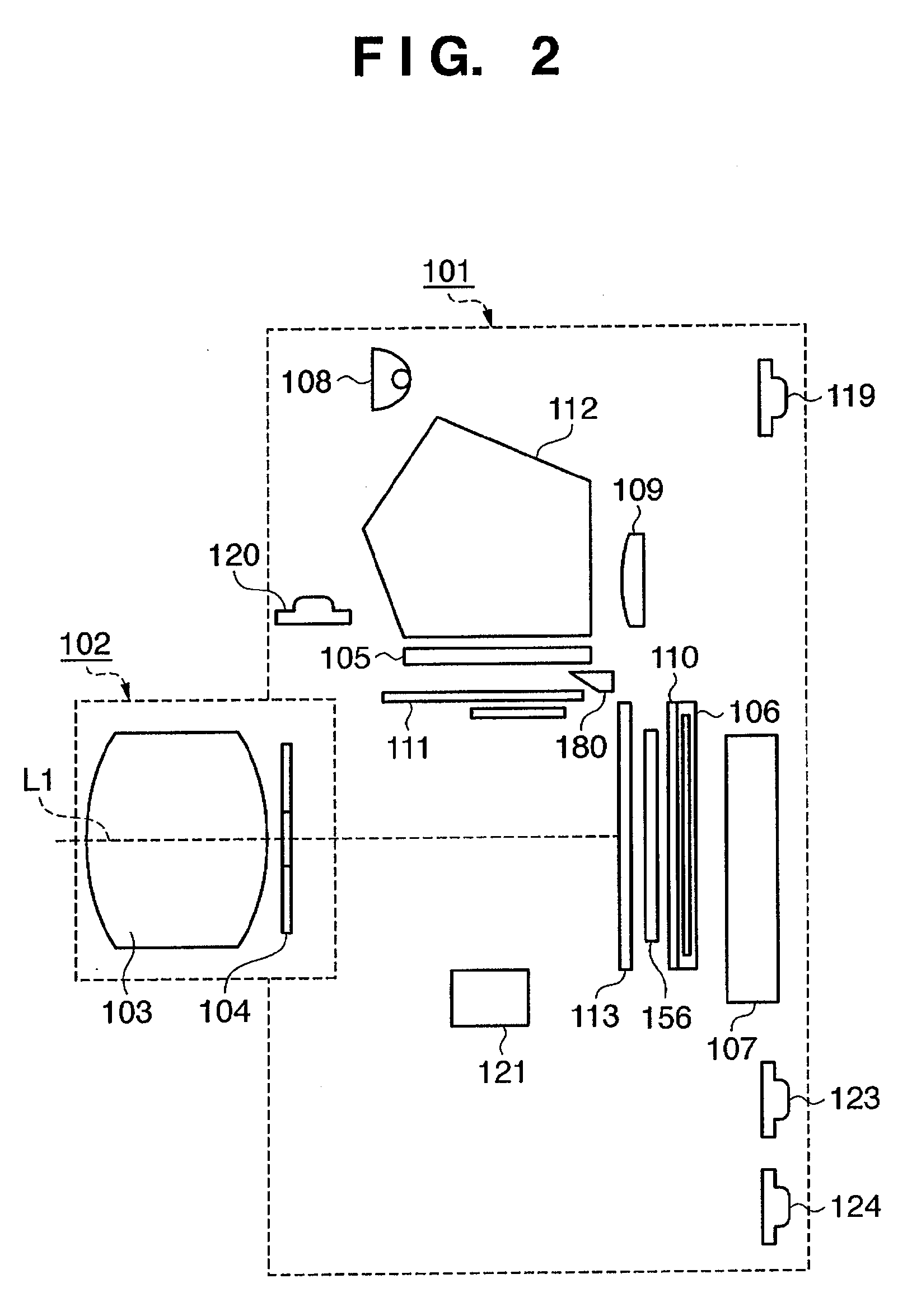
[0027]A description is now given of the configuration of a single-lens reflex digital camera as one example of an image sensing system according to an embodiment of the present invention, while referring to FIG. 1 through FIG. 3.

[0028]FIG. 1 and FIG. 2 are schematic cross-sectional views showing the configuration of a camera system of the present embodiment, including a camera body 101 and a lens device 102 that is removably attached to the camera body 101. FIG. 1 shows the camera system when observing an object with an optical viewfinder (OVF). The state shown in FIG. 1...


PUM


Abstract

An image sensing apparatus is provided with an aperture unit (104), an image sensor (106) that converts light beams entering through a photographing lens (103) and the aperture unit into electrical signals, and a display unit (107), including an electronic viewfinder mode to continuously display on the display unit images based on the electrical signals obtained by the image sensor. The image sensing apparatus has a control unit (135) that causes the aperture unit to stop down, when there is an instruction to display on the display unit an image other than the image based on the electrical signals obtained by the image sensor while in the electronic viewfinder mode.

Description

BACKGROUND OF THE INVENTION[0001]1. Field of the Invention[0002]The present invention relates to an image sensing apparatus and a control method for the image sensing apparatus, and more particularly, to an image sensing apparatus with an electronic viewfinder function.[0003]2. Description of the Related Art[0004]In a single-lens reflex camera that is one type of image sensing apparatus, when observing an object using an optical viewfinder (OVF), light beams exiting from a photographing lens are reflected by a mirror provided on an image plane side of the photographing lens and directed to an optical viewfinder that includes a pentaprism or the like. Such an arrangement enables a photographer to see an image of an object formed by the photographing lens as a normal image. At this time, the mirror is set obliquely in the photographic optical path. To photograph an image of an object from this state, the mirror is momentarily withdrawn from the photographic optical path to allow the l...

Claims


Application Information

Patent Timeline
Patent Type & Authority Applications(United States)
IPC IPC(8): G03B19/12G03B13/02G03B7/095G03B7/30G03B13/00H04N23/75
CPCG03B7/006H04N5/232H04N5/23241H04N5/23245H04N5/23293H04N23/667
Inventor KIKUCHI, HIROSHI
Owner CANON KK
Learn More