
Satellite receiver

a satellite receiver and receiver technology, applied in the field of satellite receivers, can solve the problems of reducing the overall precision of angle adjustment, affecting the accuracy of the overall adjustment, and the inability of bolt/screw locking to offer the rapid test required, so as to achieve the effect of limiting the displacemen

Active Publication Date: 2009-03-05
WISTRON NEWEB
View PDF11 Cites 50 Cited by
  • Summary
  • Abstract
  • Description
  • Claims
  • Application Information

AI Technical Summary

Benefits of technology

[0007]It is an objective of the present invention to provide a satellite receiver to rapidly execute the adjustment in the reception angle for signal.
[0008]It is another objective of the present invention to provide a satellite receiver to reduce the installation time of antenna.
[0009]It is one of the objectives of the present invention to provide a satellite receiver which facilitates the test and search for the angles of signal sources.
[0010]It is one of the objectives of the present invention to provide a satellite receiver able to rapidly return the satellite receiver to the default zero position.
[0012]The adjusting mechanism includes a rod having a connection end and an adjusting end, wherein the connection end of the rod couples with the rotation stand through the base. The connection end also moves together with the rotation stand to generate displacement relative to the base. The positioning device couples with the adjusting end of the adjusting mechanism while passing through the first slot on the base. When the rotation stand rotates relative to the base relative the axis aperture, the positioning device moves together with the adjusting mechanism, to generate displacement along the axis of the first slot. The positioning device has a pin, wherein a first end of the pin couples with the adjusting end of the adjusting mechanism, and a second end of the pin passes through the first slot. Furthermore, the positioning device can selectively limit the displacement generated by the adjusting device relative to the base. The user thus can operate and control the positioning device to fix the relative position between the adjusting mechanism and the base, or to release the positioning device in order for the adjusting mechanism to generate displacement relative to the base.

Problems solved by technology

As FIG. 1 shows, the shown elevation angle adjustor 30, azimuth rotation stand 50 and the base 70 are often locked with bolts and screws which creates difficulty in the fine-tuning of angles and also degrades the overall precision of angle adjustment.
The conventional method of bolt / screw locking cannot offer rapid test required and also cannot offer quick recovery to the default angle setting.

Method used


Image

  • Satellite receiver
  • Satellite receiver
  • Satellite receiver

Examples


Embodiment Construction

[0022]The present invention provides a wireless signal receiver. In one embodiment, the wireless signal receiver includes a satellite receiver such as a satellite antenna. However, in other embodiments, the wireless signal receiver can also include other types of antennas or signal receivers, such as a communication network antenna, a television signal antenna, a broadcast signal antenna etc. Furthermore, the satellite antenna is preferred to include a dish antenna. However, in other embodiments, the satellite antenna may also include other types or forms of antennas.

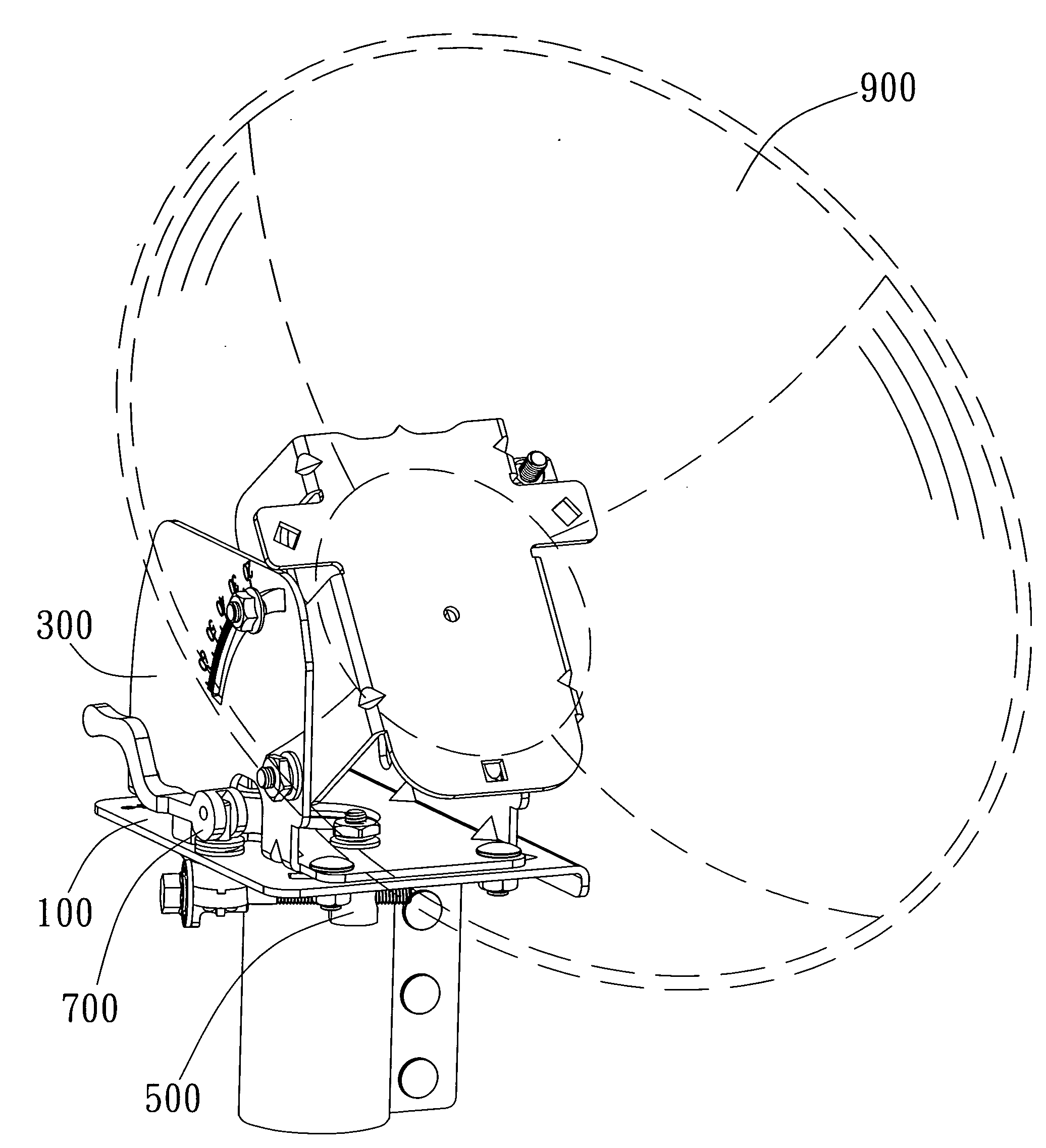
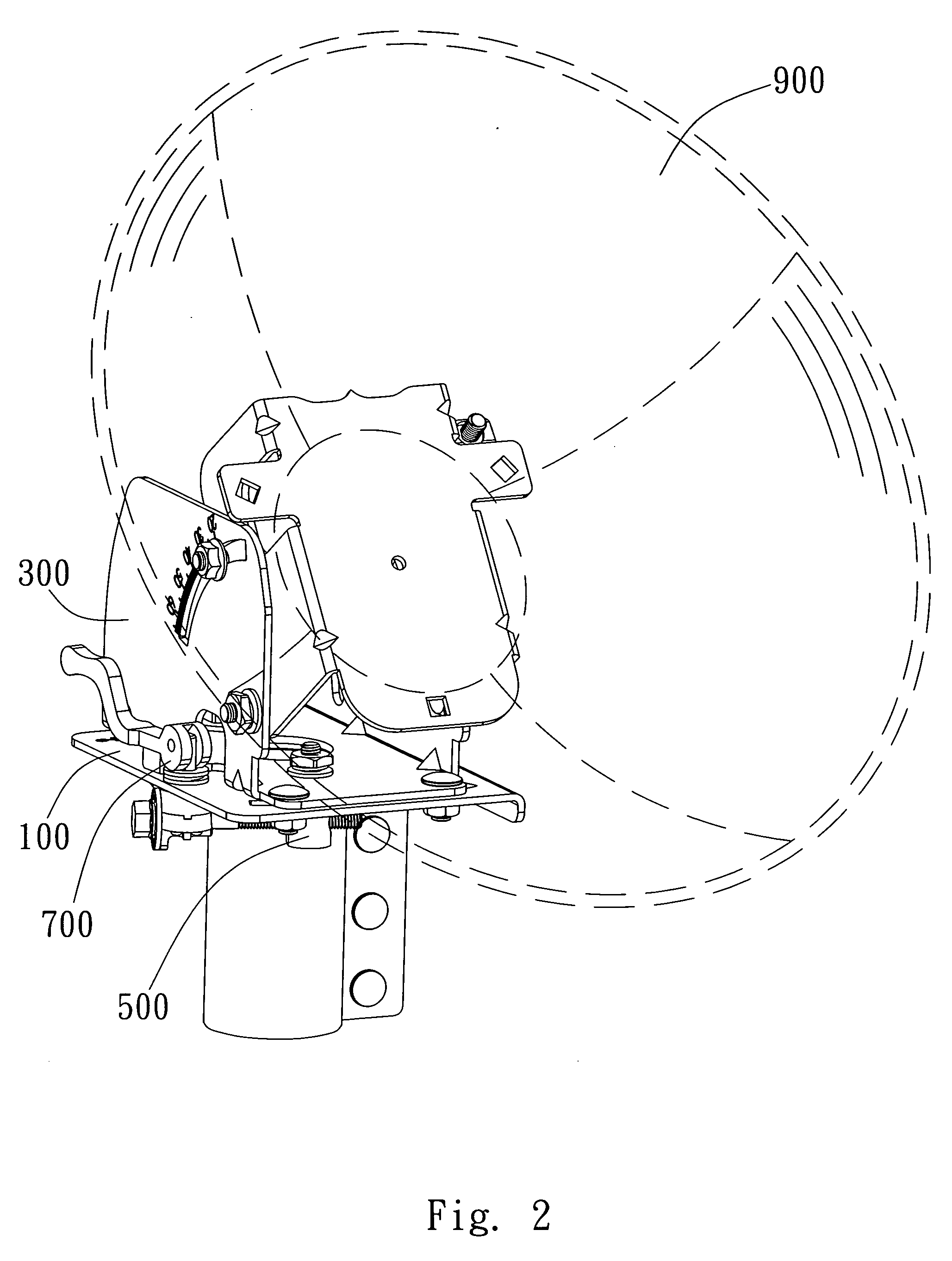
[0023]As FIG. 2 shows, the satellite receiver of the present invention comprises a base 100, a rotation stand 300, an adjusting mechanism 500 and a positioning device 700. The base 100 couples with the structure below and supports the antenna dish 900 above. In an embodiment shown in FIG. 3, an axis aperture 130 and a first slot 210 are defined on the base 100. In the present embodiment, the first slot 210 is an curved ...


PUM


Abstract

The present invention provides a satellite receiver comprising a base, a rotation stand, an adjusting mechanism, and a positioning device. The base has an axis aperture and a first slot. The rotation stand is rotatably attached to the base through the axis aperture. The adjusting mechanism has a connection end and an adjusting end. The connection end is coupled with the rotation stand and is movable together with the upper stand to generate displacement relative to the base. The positioning device is coupled with the adjusting end and passes through the first slot. When the upper stand rotates relatively to the base, the adjusting mechanism drives the positioning device to move along the first slot. The first slot limits the angular rotation of the rotation stand and the positioning device and selectively constrains the relative displacement between the connecting unit and the base.

Description

BACKGROUND OF THE INVENTION[0001]1. Field of the Invention[0002]The present invention relates to a wireless signal receiver; particularly, the present invention relates to a satellite receiver.[0003]2. Description of the Prior Art[0004]As technology advances, the technology level of wireless signal transmission and the depth of its application also reach a new level. As for the field of communication, the applications of wireless communication include personal mobile communication, broadcast, wireless network, satellite communication etc. In order to further enhance the technology development and the depth of application; the fidelity of transmitted and received wireless signal needs to be continuously improved. For instance, the reception side often needs to utilize satellite antenna as the reception device for satellite signal, and therefore the precise contraposition of antennae for improving the directivity of antenna signal has become a key factor in ensuring the quality of rec...

Claims


Application Information

Patent Timeline
IPC IPC(8): H01Q3/02H04H20/00
CPCH01Q19/12H01Q1/1264
Inventor YANG, LAN-CHUNLIN, HUNG-YUAN
Owner WISTRON NEWEB
Learn More