
Non-Volatile Memory With High Reliability

a non-volatile memory, high-reliability technology, applied in the field of non-volatile memory, can solve the problems of low cell endurance and undesired addition of control circuitry to the non-volatile memory portion, and achieve the effect of extending the expected cell endurance and reducing the average expected number of fowler-nordheim tunneling operations

Active Publication Date: 2008-11-27
SEMICON COMPONENTS IND LLC
View PDF6 Cites 7 Cited by
  • Summary
  • Abstract
  • Description
  • Claims
  • Application Information

AI Technical Summary

Benefits of technology

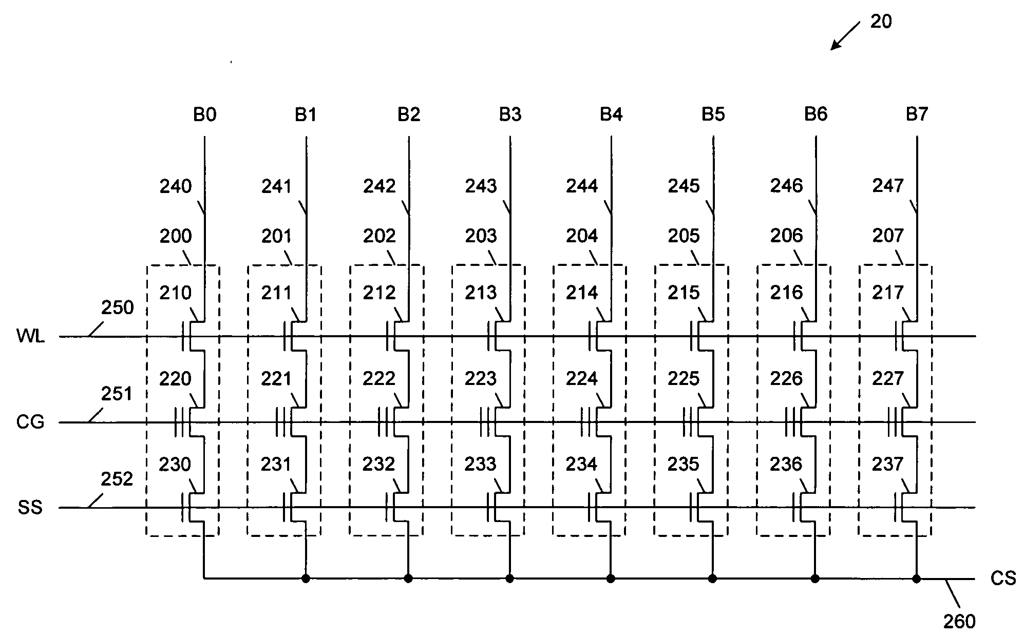
[0016]A common set of bit line voltages are applied to the bit lines during both the erase and program phases, such that it is not necessary to switch the bit line voltages between the erase and program phases. An erase voltage is applied to the control gates of the non-volatile memory transistors during the erase phase, and a program voltage, different than the erase voltage, is applied to the control gates of the non-volatile memory transistors during the program phase. During the erase phase, Fowler-Nordheim tunneling may be induced in a first subset of the non-volatile memory transistors. During the program phase, Fowler-Nordheim tunneling may be induced in a second subset of the non-volatile memory transistors, wherein the first and second subsets are mutually exclusive. Fowler-Nordheim tunneling may be inhibited in a third subset of the non-volatile memory transistors during both the erase phase and the program phase, wherein the first, second and third subsets are mutually exclusive, and include all of the non-volatile memory transistors subject to the two-phase operation. This two-phase write operation reduces the average expected number of Fowler-Nordheim tunneling operations by half, thereby extending the expected cell endurance.

Problems solved by technology

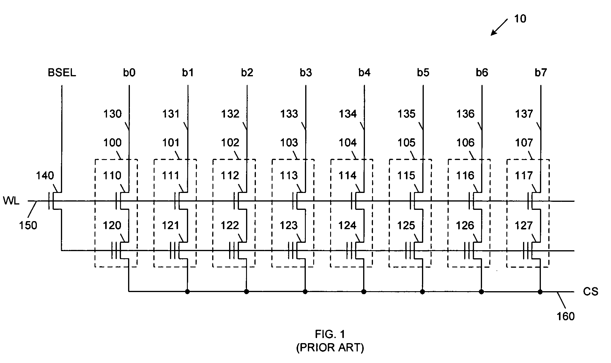
The above-described method for writing data to non-volatile memory cells 100-107 undesirably requires (on average) a large number of Fowler-Nordheim tunneling operations, thereby resulting in relatively low cell endurance.
This control circuitry undesirably adds complexity to the non-volatile memory portion 10.

Method used


Image

  • Non-Volatile Memory With High Reliability
  • Non-Volatile Memory With High Reliability
  • Non-Volatile Memory With High Reliability

Examples


Embodiment Construction

[0023]FIG. 2 is a circuit diagram of a portion 20 of a non-volatile memory system, wherein this portion 20 stores an 8-bit byte, in accordance with one embodiment of the present invention. Non-volatile memory portion 20 includes non-volatile memory cells 200-207, bit lines 240-247, word line 250, control gate line 251, source select line 252 and common source line 260. Non-volatile memory cells 200-207 include n-channel access transistors 210-217, n-channel non-volatile memory transistors 220-227, and n-channel source select transistors 230-237. Each of the non-volatile memory transistors 220-227 includes a floating gate for storing charge in a manner well known to those of ordinary skill in the art. It is understood that non-volatile memory portion 20 could be expanded to create an array having additional rows and / or columns, in other embodiments of the present invention.

[0024]The drains of access transistors 210-217 are coupled to bit lines 240-247, respectively. The sources of ac...


PUM


Abstract

A non-volatile memory (NVM) system includes a set of NVM cells, each including: a NVM transistor; an access transistor coupling the NVM transistor to a corresponding bit line; and a source select transistor coupling the NVM transistor to a common source. The NVM cells are written by a two-phase operation that includes an erase phase and a program phase. A common set of bit line voltages are applied to the bit lines during both the erase and programming phases. The access transistors are turned on and the source select transistors are turned off during the erase and programming phases. A first control voltage is applied to the control gates of the NVM transistors during the erase phase, and a second control voltage is applied to the control gates of the NVM transistors during the program phase. Under these conditions, the average required number of Fowler-Nordheim tunneling operations is reduced.

Description

RELATED APPLICATION[0001]The present application is related to, and claims priority of, U.S. Provisional Patent Application Ser. No. 60 / 940,376 filed by A. Peter Cosmin, Sorin S. Georgescu, George Smarandoiu and Adrian M. Tache on May 25, 2007.FIELD OF THE INVENTION[0002]The present invention relates to a non-volatile memory that exhibits high reliability and endurance in view of repeated write operations.RELATED ART[0003]FIG. 1 is a circuit diagram that illustrates a portion 10 of a conventional non-volatile memory array, wherein this portion 10 stores an 8-bit byte. Non-volatile memory array portion 10 includes non-volatile memory cells 100-107, bit lines 130-137, byte select transistor 140, word line 150 and common source line 160. Non-volatile memory cells 100-107 include n-channel access transistors 110-117, and n-channel non-volatile memory transistors 120-127. Each of the non-volatile memory transistors 120-127 includes a floating gate for storing charge in a manner well know...

Claims


Application Information

Patent Timeline
IPC IPC(8): G11C16/04
CPCG11C16/0433G11C11/34G11C16/10G11C16/14G11C16/24
Inventor COSMIN, A. PETERGEORGESCU, SORIN S.SMARANDOIU, GEORGETACHE, ADRIAN M.
Owner SEMICON COMPONENTS IND LLC
Learn More