Eureka AIR delivers breakthrough ideas for toughest innovation challenges, trusted by R&D personnel around the world.

Lid opening and closing system

Active Publication Date: 2008-11-27
PIOLAX CO LTD
View PDF2 Cites 17 Cited by
  • Summary
  • Abstract
  • Description
  • Claims
  • Application Information

AI Technical Summary

Benefits of technology

[0009]An object of the present invention is to provide a lid opening and closing system which can ensure that a lid is opened from a recess on a body by causing a pushing force from the user to act on a lock pin effectively.
[0012]As this occurs, since the pushing element pushes at the lock pin by the slope provided at least one of the abutting surfaces not only in the direction in which the lock pin is caused to retreat in the lid's side but also in the direction in which the lid is opened, when the lock pin is pulled out from the engagement hole provided on the inner circumference of the recess, the force is exerted which acts in the direction in which the lid is opened, whereby the lid can be opened in a smooth fashion. Consequently, even though a state results in which a frictional force is exerted between the lid and the recess, making it difficult for the lid to open by gravity, the lid can be opened in an ensured fashion.
[0014]According to such a configuration, since when the lock pin is pushed into the lid's side by the pushing element to thereby release the locked state, the pushing element contacts the part of the lid so as to impart the pushing force in the direction in which the lid is opened, the lid can be opened in a more ensured fashion.
[0016]According to such a configuration, the mechanism which is linked with the push button to cause the pushing element to move in the opposite direction to the direction in which the push button is pushed can be realized by a relatively simple mechanism and in a space saving fashion.
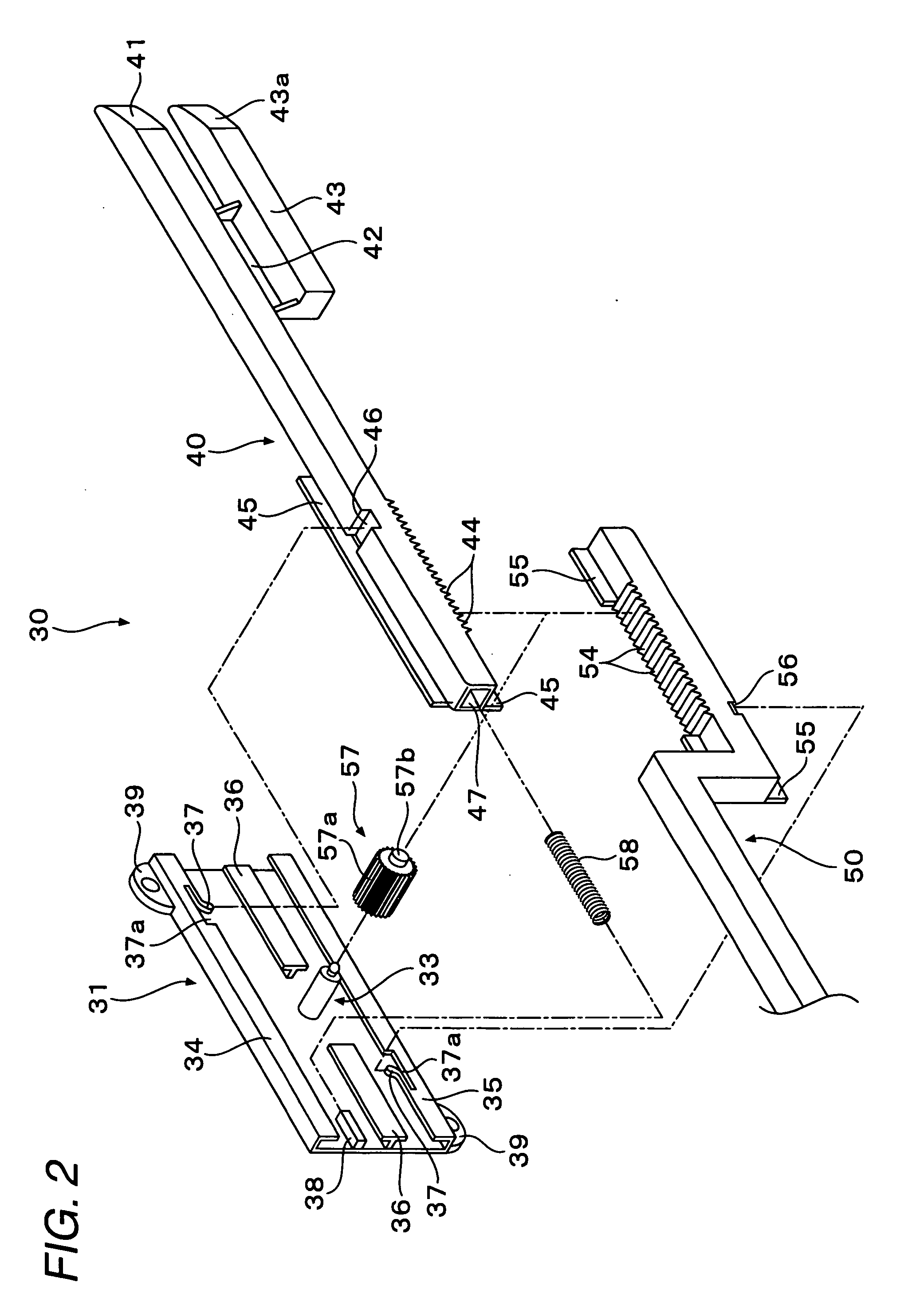
[0020]According to such a configuration, the push pin of the pushing element is made to push at not the pin portion which is engaged with the engagement hole but at the receiving portion which is different from the pin portion, so as to cause the lock pin to retreat toward the lid. Therefore, an angle of the distal end portion of the receiving portion with respect to the longitudinal side face of the lock pin can be changed while keeping the shape of the pin portion. That is, the angle of the distal end portion of the receiving portion can be set to change a ratio between a moving amount of the lock pin and a moving amount of the pushing pin while ensuring a sufficient locking condition. For example, when the angle is formed gently, the pushing stroke of the push button required to release the lock state can be reduced. On the other hand, when the angle is formed steeply, the pushing force of the push button can be reduced.
[0024]According to such a configuration, since the pushing element slope is formed at a less steep inclination angle than the pin slope relative to the longitudinal side face of the lock pin, when the pushing element is driven to move in conjunction with the operation of the push button to push at the pushing element slope, the lock pin can be caused to move largely relative to the moving amount of the pushing element. On the other hand, since the pin slope is formed at a steeper angle relative to the longitudinal side face of the lock pin, the pin slope contacts the peripheral edge of the recess, so that the lock pin can be caused to retreat inwards of the lid in a smooth fashion.

Problems solved by technology

In the glove box opening, closing and locking system, however, when a frictional force is exerted between a peripheral edge of the recess on the automobile side and the lid due to the lid being distorted or warped, even though the lock portions are caused to retreat inwards of the lid so as to unlock the lid, there sometimes occurs a situation in which the lid is not opened by gravity.
However, since the two tapered surfaces 4a, 4b are involved in the pushing action from when the operation button 1 is pushed to when the pushing force of the operation button 1 is transmitted to the lid 2, the force acting in the direction in which the lid 2 is opened is weakened, leading to a problem that the pushing force of the operation button 1 is made difficult to act effectively as the force with which the lid 2 is opened.

Method used


Image

  • Lid opening and closing system
  • Lid opening and closing system
  • Lid opening and closing system

Examples


first embodiment

[0043]Embodiments of the present invention will be described by reference to the drawings. FIGS. 1 to 11 show a

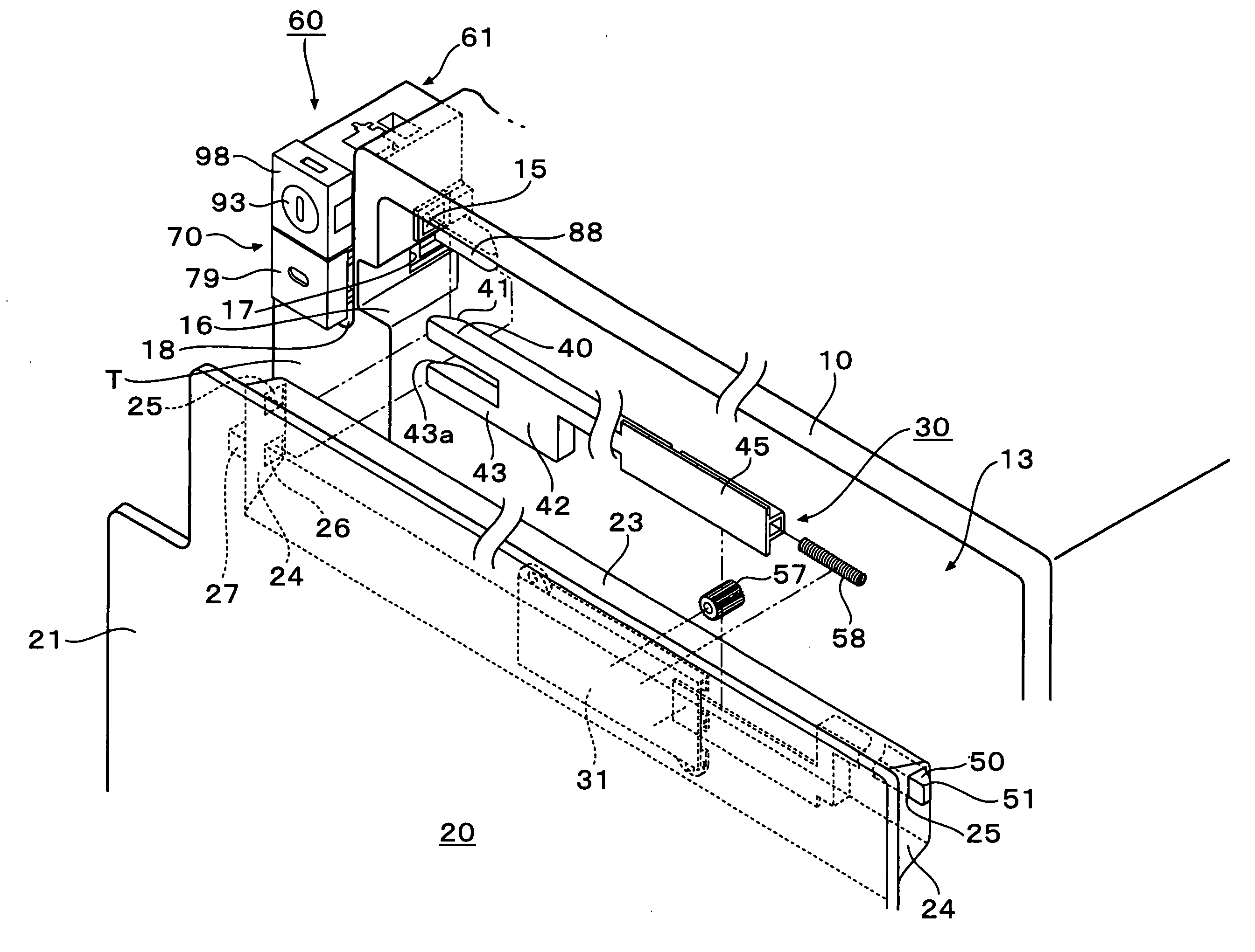
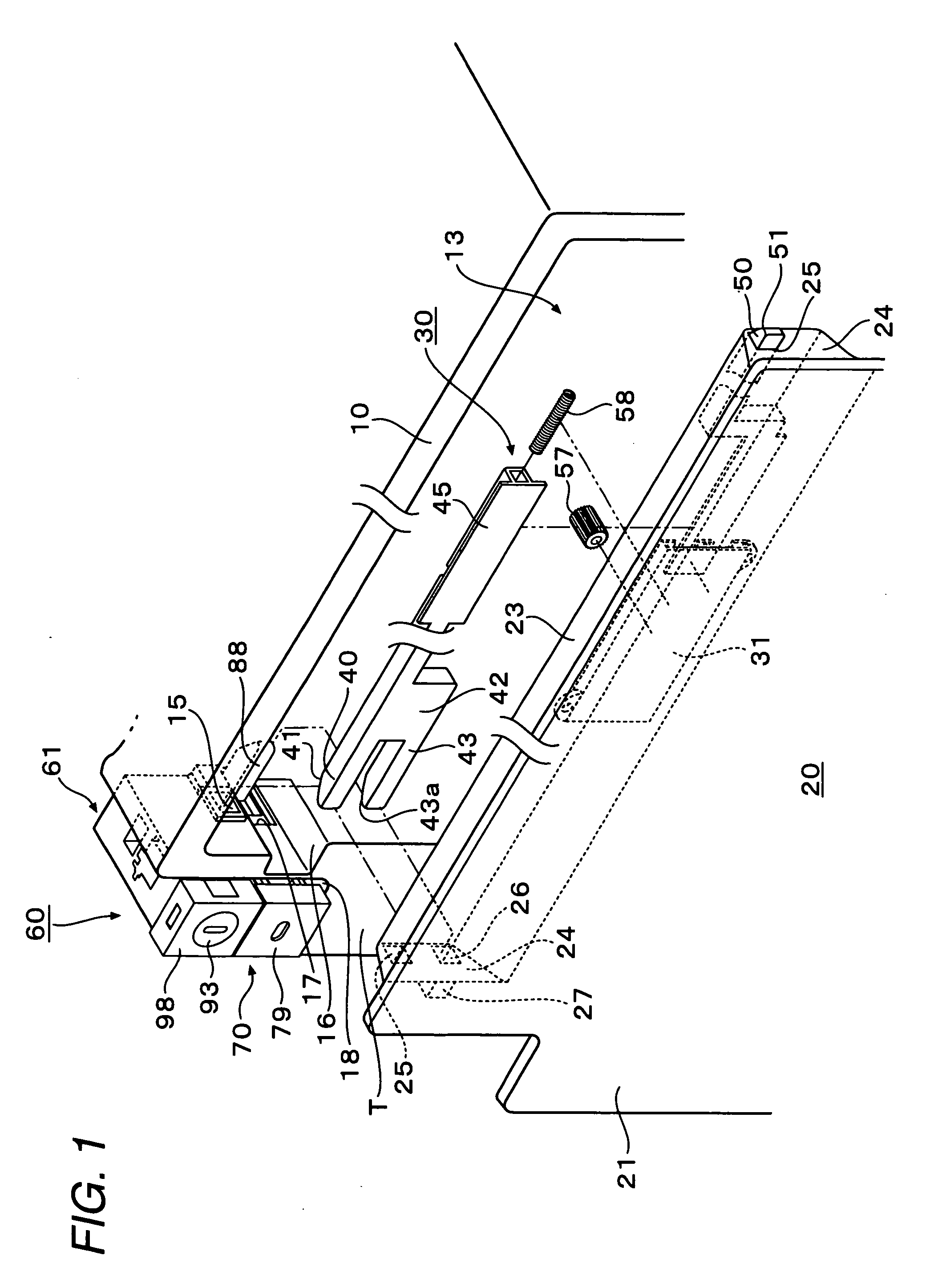
[0044]As is shown in FIG. 1, this lid opening and closing system includes a lid 20 which is mounted in a recess 13 formed on an automobile in such a manner as to be opened and closed, a lock unit 30 for locking the lid 20 in a closed state, and a lock releasing unit for releasing the locked state of the lid 20 by the lock unit 30. In the embodiment, the recess 13 is such as to be formed into a box-shaped glove box 10 which is fixedly provided in an instrument panel of the automobile. Note that there is imposed no specific limitation on the recess 13, and the recess 13 may be such a recess as provided on a side wall or a bottom wall in a passenger compartment of the automobile.

[0045]As is shown in FIG. 1, the recess 13 is formed into a laterally elongated shape, and a pair of engagement holes 15, is provided on both left- and right-hand sides of the recess 13 so that a pair ...

second embodiment

[0087]FIG. 12 shows a lid opening and closing system according to a Note that like reference numerals are imparted to substantially like portions to those of the embodiment that has been described above, and the description thereof will be omitted.

[0088]In the embodiment above, the mechanism to move the pushing element by being linked with the operation of the push button is made up by the rack and pinion mechanism. This embodiment differs from the previous embodiment in that the mechanism to move the pushing element is made up of a link lever mechanism.

[0089]As is shown in FIG. 12, in a lock releasing unit 60a of this embodiment, a push button 70a is mounted on a case main body 61a in such a manner as to slide relative thereto via a slide guide, not shown, and a coil spring 69a is interposed between a rear end portion of the push button 70a and a rear wall of the case main body 61, whereby the push button 70a is urged in a direction in which it moves away from a front side of the ...

third embodiment

[0091]FIG. 13 shows a lid opening and closing system according to a Note that like reference numerals are imparted to substantially like portions to those of the embodiment that has been described above, and the description thereof will be omitted.

[0092]In the embodiments described above, the pushing element 80 pushes at the pushing element receiving portion 43. On the other hand, in this embodiment, a distal end portion of a lock pin which is brought into engagement with an engagement hole 15 on an inner circumference of a recess 13 is made to be pushed directly.

[0093]In this embodiment, a circumferential wall of a glove box 10 differs from those of the embodiments described above. Namely, a passage hole 10a is formed in a wall surface on a front side, and front and rear walls 11, 12 which lie on both peripheral edges of an engagement hole 15a are such that the rear wall 12 (the edge portion which lies farther apart from a lid) is provided further inwards of the lid 20 than the fr...


PUM


Abstract

According to an aspect of the present invention, there is provided a lid system including: a lid mounted to a recess to be opened and closed; a locking unit that retains the lid in a locked state to keep the lid closed; and a lock releasing unit that releases the locked state to open the lid. The locking unit includes: a pin that is protruded from a peripheral edge of the lid to be engaged with a hole on the recess in the locked state and retreated to release the locked state. The lock releasing unit includes: a push button pushable in a pushing direction; and a pushing element moved to push the lock pin in an opposite direction of the pushing direction by being linked with the push button.

Description

CROSS-REFERENCE TO RELATED APPLICATIONS[0001]This application claims priority from Japanese Patent Application No. 2007-135612 filed on May 22, 2007, and from Japanese Patent Application No. 2008-126881 filed on May 14, 2008, the entire contents of which are incorporated herein by reference.BACKGROUND OF THE INVENTION[0002]1. Field of the Invention[0003]An aspect of the present invention relates to a lid opening and closing system for opening and closing a lid of a glove box, for example, from and to a recess formed on an automobile.[0004]2. Description of the Related Art[0005]For example, a glove box is provided in front of a front passenger's seat of an automobile to be opened and closed, and as a means for opening, closing and locking a lid of a glove box of this type relative to a recess provided on an automobile's side, JP-A-2005-104192 discloses a glove box opening, closing and locking system having an operating portion which is mounted on an instrument panel side and provided...

Claims


Application Information

Patent Timeline
IPC IPC(8): B62D25/12B60R7/06E05C21/00E05B83/30
CPCE05B1/0038E05B63/242E05B83/30E05C9/041Y10T292/1064B60R7/06E05C21/00
Inventor OHNUKI, TOMOYOSHI
Owner PIOLAX CO LTD
Why Eureka
Eureka Blog
Learn More