
Power matching method

a matching method and power technology, applied in the direction of optical radiation measurement, instruments for comonautical navigation, instruments, etc., can solve the problems of inability to sufficiently quickly, less optimal working point set, and change in edge conditions quite quickly, so as to achieve the effect of convenient performan

Active Publication Date: 2008-11-27
SMA SOLAR TECH AG
View PDF5 Cites 38 Cited by
  • Summary
  • Abstract
  • Description
  • Claims
  • Application Information

AI Technical Summary

Benefits of technology

[0009]It is the object of the invention to indicate a method that is suited for both stationary generator characteristic curves and non stationary generator characteristic curves and that is easy to perform so that the best working point is set even if there are external interfering factors.

Problems solved by technology

In practice however, the problem is that the edge conditions may change quite quickly through varying meteorological impact.
The method mentioned may not be able to sufficiently quickly detect the interfering factors so that the working point set may be less optimal.
If the edge conditions are never stationary, mismatches or even the setting of the idle or short-circuit point are possible so that the power flow collapses completely.
If the generator characteristic curve is not stationary, for example due to quickly changing meteorological conditions, this method does not find the maximum power point.

Method used


Image

  • Power matching method
  • Power matching method
  • Power matching method

Examples


Embodiment Construction

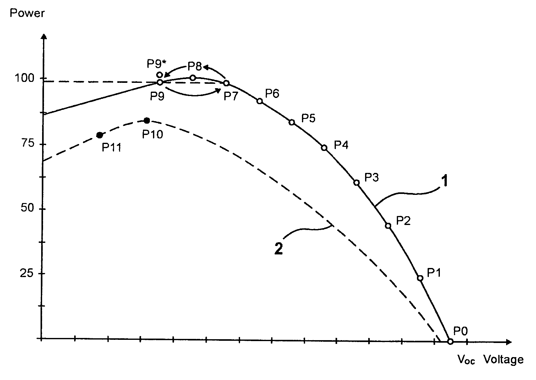
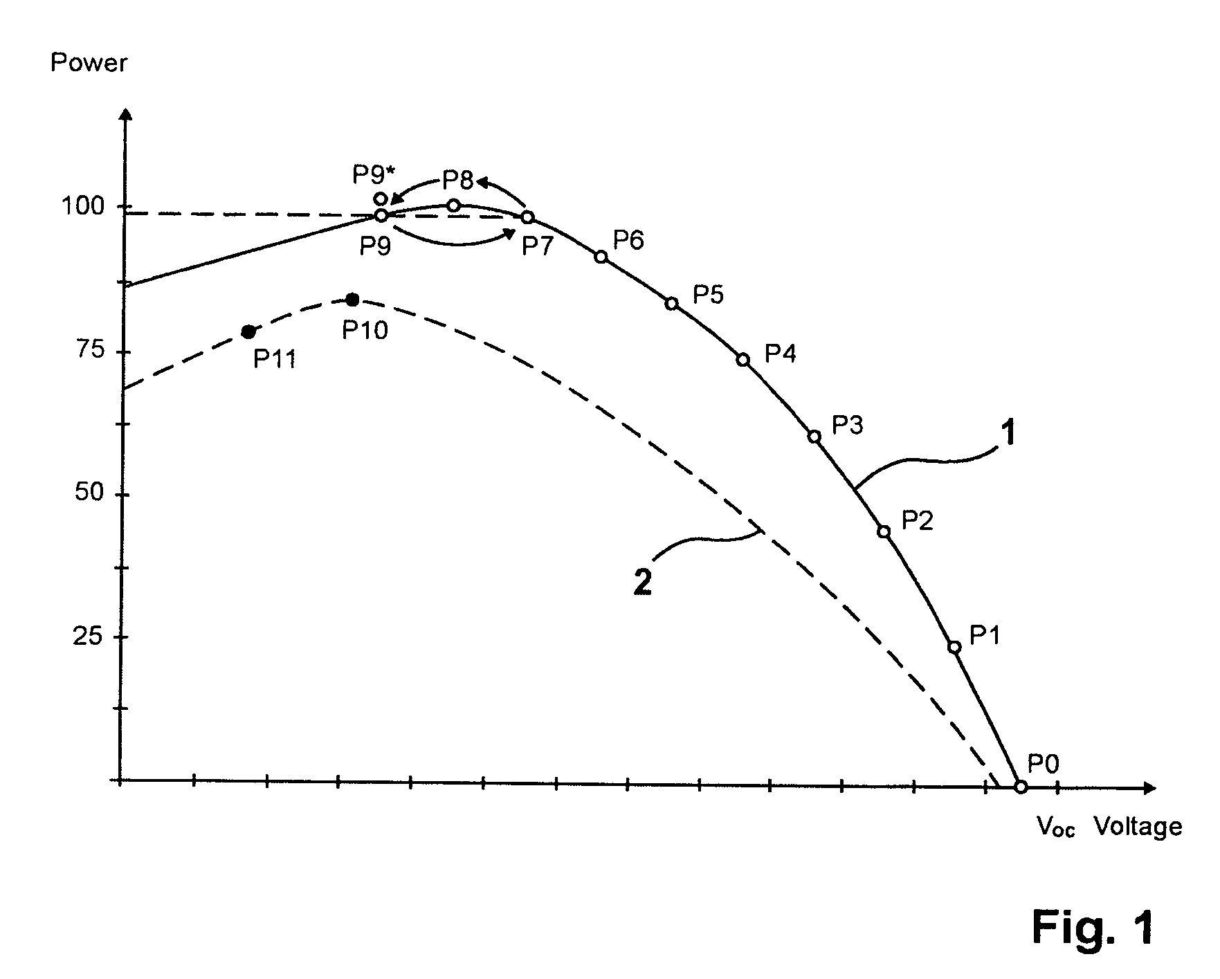
[0036]FIG. 1 shows a first generator characteristic curve1 of a photovoltaic system with a photovoltaic inverter and with a DC-AC photovoltaic inverter for electrical energy production. For setting the best working point, a basic method implemented as a slope method is being utilized.

[0037]The slope method, which is being utilized as a basic method, will first be described to garner a better understanding. At first, it is assumed that the generator operates under stationary conditions or that the radiation striking the generator is constant whilst the working point is being set. At first, the generator is not yet in operation so that the voltage applied at the input is an idle voltage Voc, the working point being indicated at P0.

[0038]The power begins to be delivered with a target value, e.g., a voltage target value, being dictated that is smaller than the idle voltage Voc. Successively, the target value is gradually lowered so that the generator power increases as a result thereof....


PUM


Abstract

A method of matching the power of a photovoltaic system producing electric energy by which a working point at which the system produces maximum power is set by changing the working point in an MPP matching process and by comparing the system power, which changes as a result thereof, is intended to be suited both for stationary characteristic curves and for non stationary generator characteristic curves and to be easy to carry out so that the best working point is always set, even when the system is subjected to external interfering factors. This is achieved in that one or several additional control steps or control cycles are performed in order to track during the matching process a power point changing under external impact for a working point of even higher power to be set.

Description

CROSS-REFERENCE TO RELATED APPLICATIONS[0001]This application claims Priority from European Application No. EP 07010197.7 filed May 23, 2007FIELD OF THE INVENTION[0002]The invention relates to a method for matching the power of a system producing electric energy by which a working point at which the system produces maximum power is set by changing the working point in an MPP matching process and by comparing the system power, which changes as a result thereof.[0003]Photovoltaic generators consist of photovoltaic cells or of what are referred to as solar cells which, by virtue of their semi-conductor properties, comprise particular generator characteristic curves. The peak power that may be delivered depends heavily on the working point of the generator characteristic curve. Since precious and expensive electric energy gets lost if wrongly matched, one tries to optimally is match the working point using matching methods. For, the working point depends not only on the electric load bu...

Claims


Application Information

Patent Timeline
IPC IPC(8): G01C21/02
CPCG05F1/67Y02E10/58Y02E10/56
Inventor LEONHARDT, GERALDKUHNEL, CHRISTIANLASCHINSKI, JOACHIMBREMICKER, SVENAREND, OLIVERBETTENWORT, GERDREICHENBACHER, WOLFGANG KURT
Owner SMA SOLAR TECH AG
Learn More