Facial plane relator

a technology of relator and face, applied in the field of facial plane relator, can solve the problem that the face relator may even not be aligned accurately with the face of the patient, and achieve the effect of improving the accuracy of the patient's fa

Inactive Publication Date: 2008-11-13
HO PHILLIP P
View PDF2 Cites 0 Cited by
  • Summary
  • Abstract
  • Description
  • Claims
  • Application Information

AI Technical Summary

Benefits of technology

[0012]The primary objective of the present invention is to provide a facial plane relator that allows an operational staff to align conveniently and accurately the facial plane with a patient's face for manufacturing a symmetrical and esthetic denture.
[0014]Therefore, the operational staff can align conveniently and accurately the facial plane relator with patient's face through the vertical and horizontal openings without moving the facial plane relator.

Problems solved by technology

The operational staff may have to move the facial plane relator to see the lines on patient's face, so it is inconvenient for the operational staff to align the facial plane relator and the facial plane relator may even not be aligned accurately with patient's face.

Method used


Image

  • Facial plane relator
  • Facial plane relator
  • Facial plane relator

Examples


Embodiment Construction

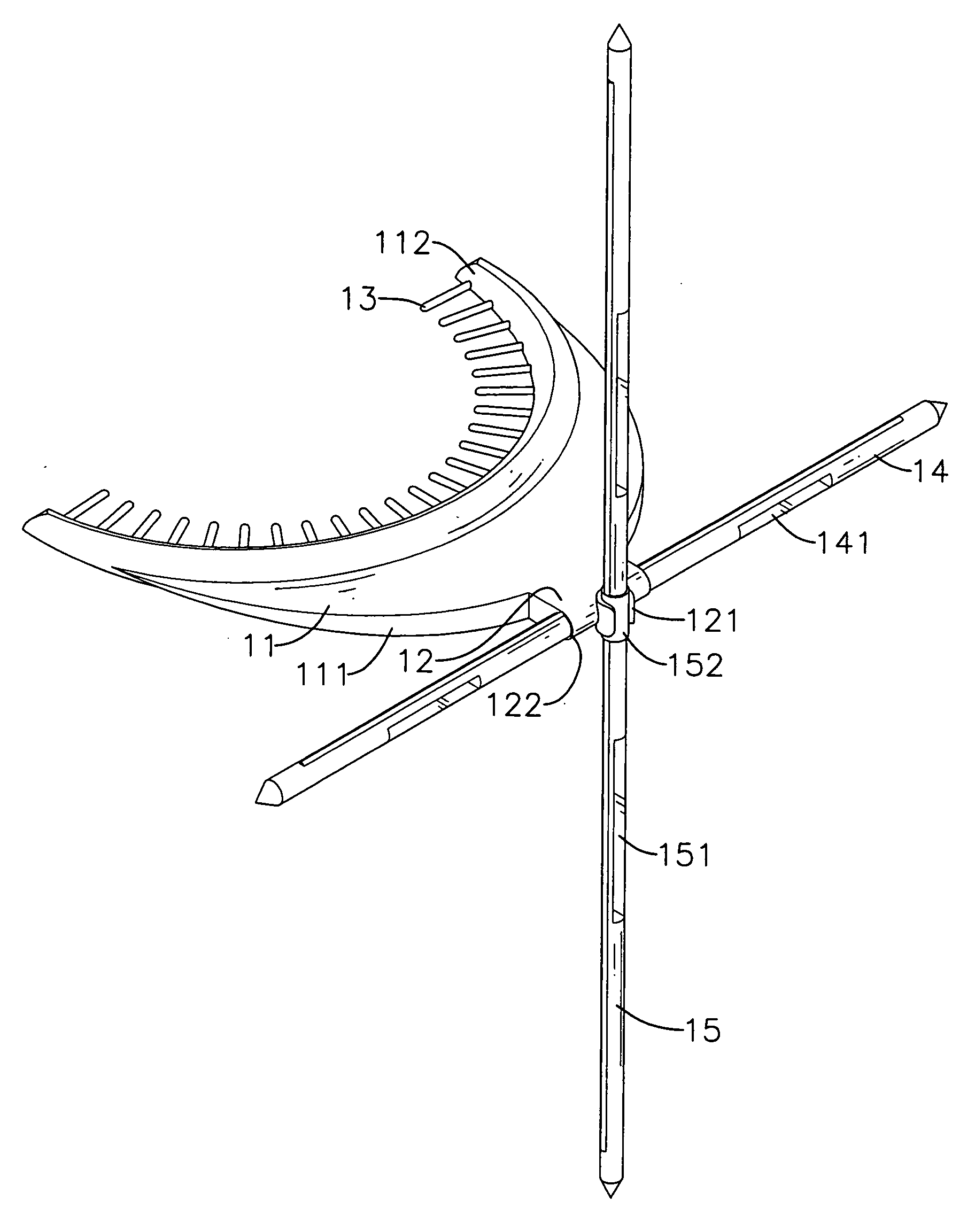
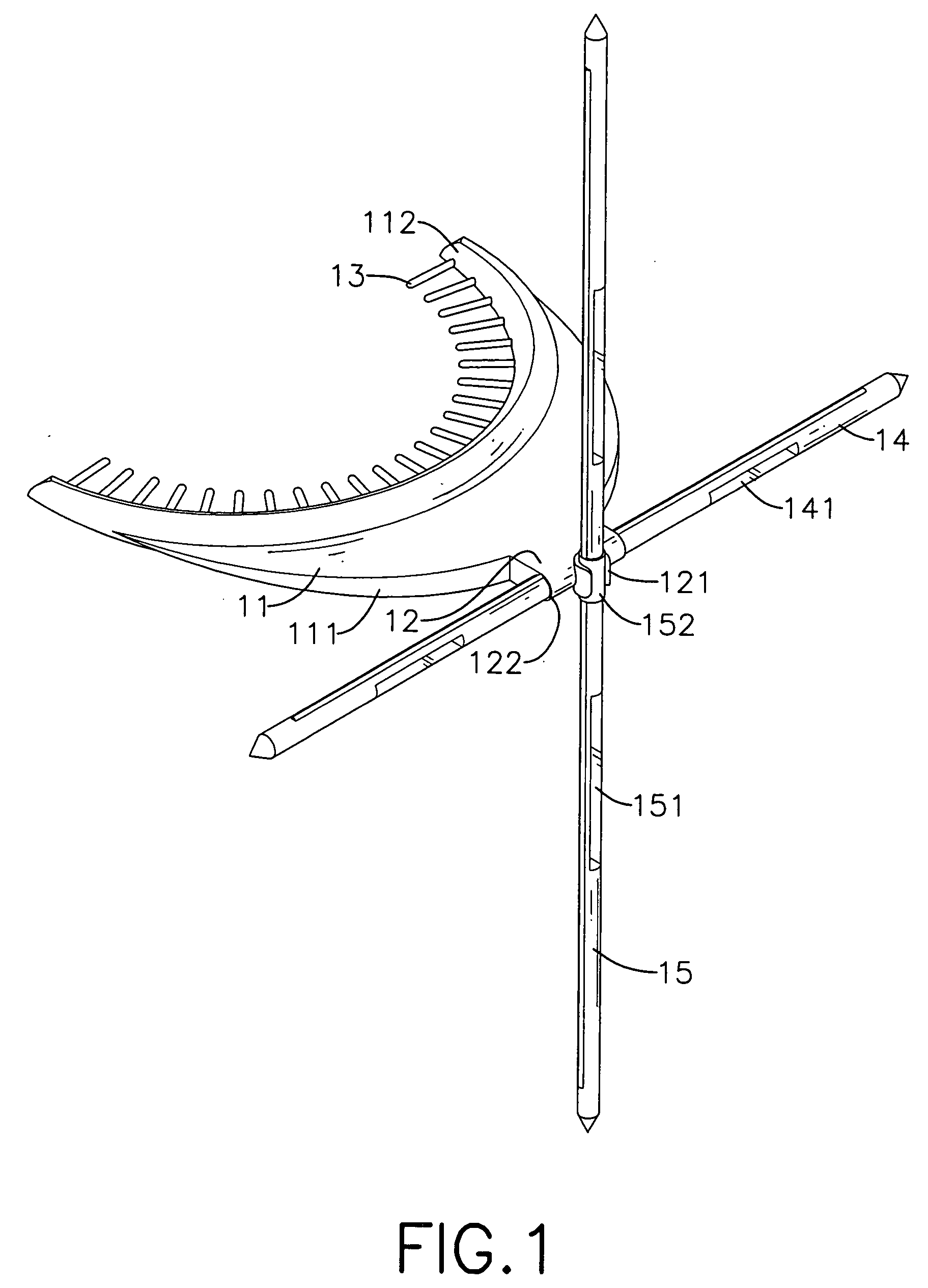
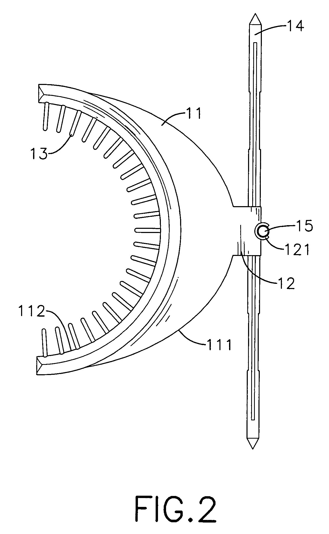
[0022]With reference to FIGS. 1 and 2, a facial plane relator in accordance with the present invention has an arch (11), a horizontal plane (14) and a vertical plane (15).

[0023]The arch (11) has an outer edge (111) and an inner edge (112). The outer edge (111) of the arch (11) has a central part and a protrusion (12). The protrusion (12) protrudes from the central part of the outer edge (111) of the arch (11) and has two ends, an outer edge, a through hole (122) and a clamp (121). The outer edge of the protrusion (12) is opposite to the outer edge (111) of the arch (11). The through hole (122) is defined transversely through the ends of the protrusion (12). The clamp (121) may be U shaped and is mounted on the outer edge of the protrusion (12). The inner edge (112) of the arch (11) has twenty-five fingers (13). The fingers (13) protrude from the inner edge (112) of the arch (11) and are arranged on the inner edge of the arch (11) at intervals.

[0024]With further reference to FIG. 5, ...


PUM


Abstract

A facial plane relator has an arch, a horizontal plane and a vertical plane. The arch has an outer edge with a protrusion having two ends, an outer edge, a through hole and a clamp. The through hole is defined transversely through the ends of the protrusion. The clamp is mounted on the outer edge of the protrusion. The horizontal plane is mounted longitudinally in the through hole and has a front, a rear and two horizontal openings defined through the horizontal plane from the front to the rear. The vertical plane is clamped by the clamp of the arch, allows the vertical plane to be perpendicular to the horizontal plane and has a front, a rear and two vertical openings defined through the vertical plane from the front to the rear. The facial plane relator is aligned conveniently and accurately with patient's face through the vertical and horizontal openings.

Description

BACKGROUND OF THE INVENTION[0001]1. Field of Invention[0002]The present invention relates to a facial plane relator, and more particularly to a facial plane relator that allows an operational staff to align conveniently and accurately the facial plane with a patient's face for manufacturing a symmetrical and esthetic denture.[0003]2. Description of the Related Art[0004]As prosthodontic technique proceeds, an edentulous patient not only wants to have a practical denture, but also wants the denture natural and esthetic. Therefore, when the operational staff make a model for the patient, they must have the model relative to patient's face to make sure that the patient will smile with neat denture symmetrical with patient's face.[0005]With reference to FIG. 6, a conventional facial plane relator has an arch (21), a horizontal plane (24) and a vertical plane (25).[0006]The arch (21) has an outer edge and an inner edge. The outer edge of the arch (21) has a central part and a protrusion (...

Claims


Application Information

Patent Timeline
IPC IPC(8): A61C19/04
CPCA61C19/04A61C19/045
Inventor HO, PHILLIP P.
Owner HO PHILLIP P
Why Eureka
Try Eureka