
Synchronizer ring

a technology of synchronizer rings and synchronizers, applied in the direction of friction linings, mechanical actuated clutches, transportation and packaging, etc., can solve the problems of transmission oil not being sufficiently displaced, disadvantageous failure of friction layers to withstand thermal conditions, and high complexity of weaving operations, etc., to achieve the effect of improving service li

Inactive Publication Date: 2008-11-13
DIEHL METAL STIFTUNG & CO KG
View PDF8 Cites 7 Cited by
  • Summary
  • Abstract
  • Description
  • Claims
  • Application Information

AI Technical Summary

Benefits of technology

[0013]It is an object of the present invention to provide a wear-resistant synchronizer ring with a friction layer made from a material comprising carbon fibers, which has an improved service life compared to the prior art and is inexpensive.
[0019]Surprisingly, it has been found that a carbon fiber reinforced plastic increases the service life of the synchronizer ring if it is compacted. This can take place during the production process or at the end of it. The material is in this way compressed such that it is protected against further compression during the gearshift or synchronization operations. Therefore, the reduction in the axial gap is not promoted by the material being pressed together. Contrary to the previously held convictions of the specialist world, however, a compacted or compressed material of this type is not subject to any deterioration in its friction properties as a result of the friction partner floating. Surprisingly, it has been found that despite the compacting of the material, when the friction layer is used on the conical friction surface of the synchronizer ring, the transmission oil can be sufficiently pressed away from the friction surface. A coefficient of friction is quickly built up. Evidently, the remaining structures of the fibers and the residual porosity in the surrounding material are sufficient to achieve this.
[0024]Then, the material is advantageously heat-treated in such a manner that part of the resin is converted into carbon, the carbon being in amorphous and / or graphite form. The temperatures for this are between 900 and 1200° C. This preferably takes place under inert gas atmosphere. A carbon content in the resin improves the friction properties. The reserve displacement loss is also reduced. The proportion of carbon can be increased if further resin is supplied by impregnation or injection after the heat treatment and the working steps of the heat treatment are repeated.
[0025]It has been found that the carbon is washed out over the duration of use of the friction layer. This reduces the wear resistance of the friction layer. This problem can advantageously be avoided by the converted carbon finally being fixed by resin.

Problems solved by technology

However, under high stresses, this friction layer disadvantageously fails to withstand the thermal conditions which are then present.
Also, the transmission oil cannot be sufficiently displaced, with the result that the friction partner floats, thereby reducing the friction.
The weaving operation, however, is highly complex and a friction layer of this type is expensive to produce.
The friction layer is produced by means of the relatively complex and therefore expensive chemical vapor deposition (CVD) process.
On account of the loss of axial reserve displacement, there is a risk of a shortened service life or of premature failure.

Method used


Image

  • Synchronizer ring
  • Synchronizer ring
  • Synchronizer ring

Examples


Embodiment Construction

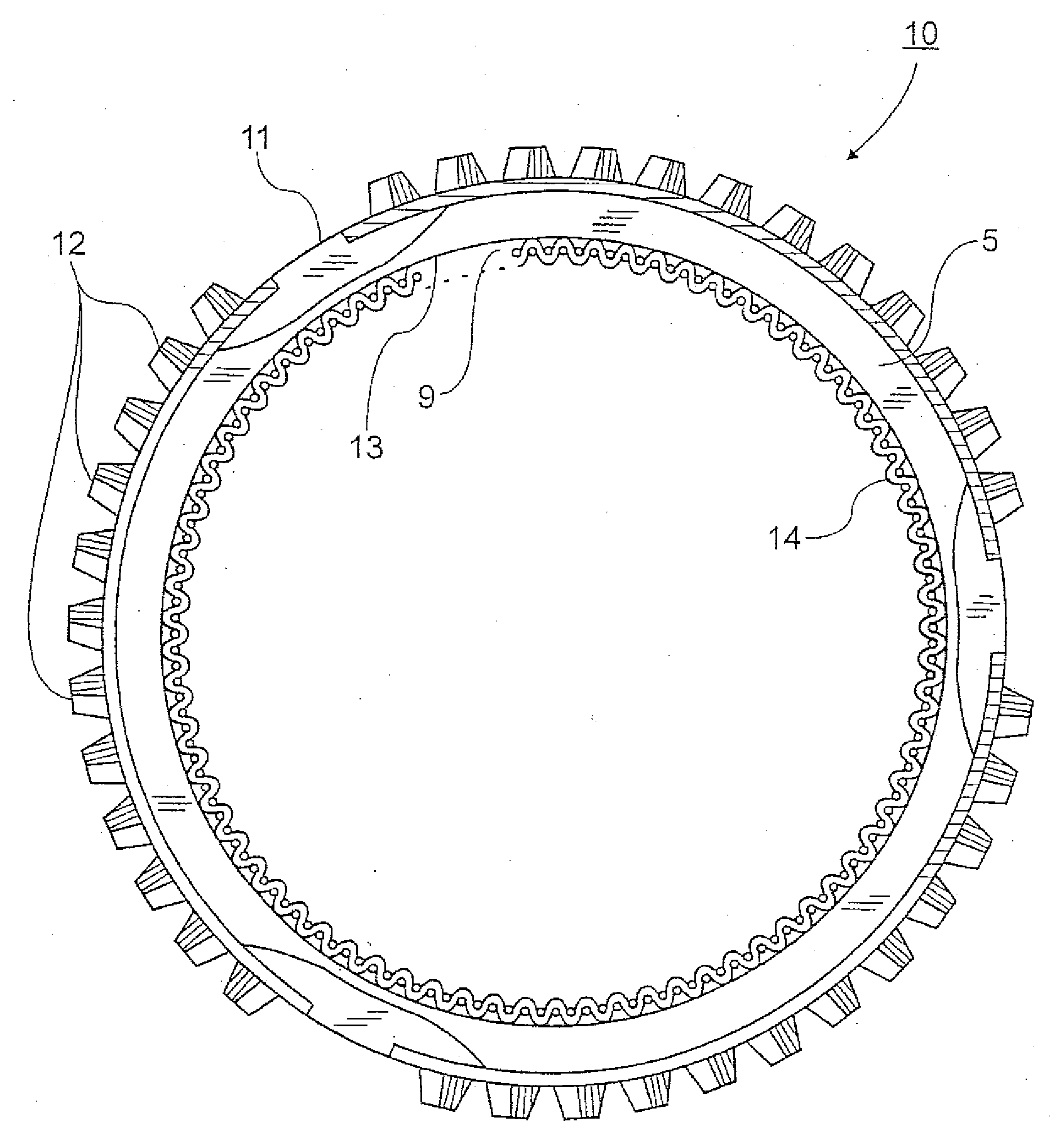
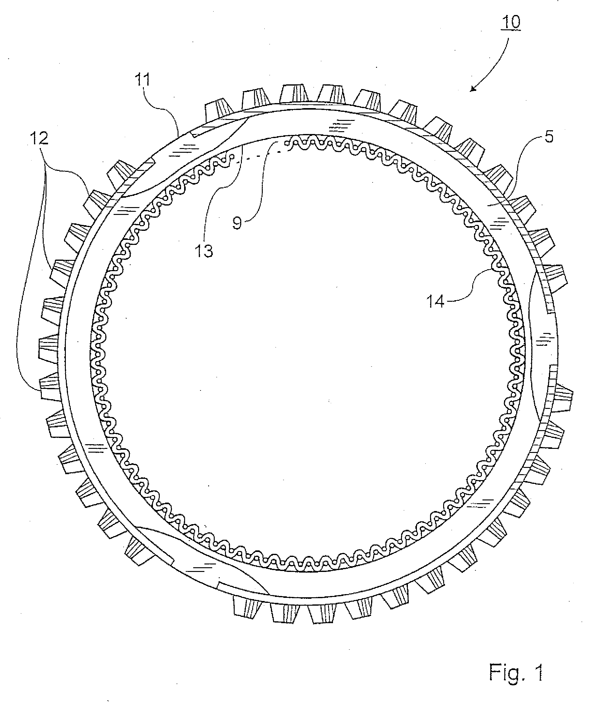
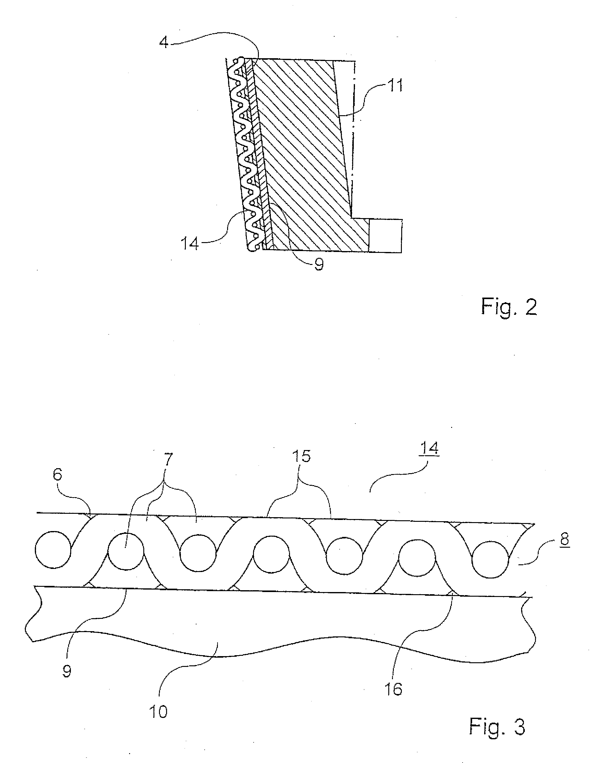
[0032]FIG. 1 shows a plan view of a synchronizer ring 10, the outer circumference 11 of which has teeth 12 as a formation which mechanically meshes with a gearwheel (not shown) of a transmission. On the inner circumference 13 of the synchronizer ring 10 is a conical friction surface 9, to which a friction layer 14 is attached. The friction layer 14 is positioned opposite a friction partner (not shown) which has a rotational speed relative to the synchronizer ring 10. During a gearshift actuation, the friction layer 14 comes into contact with the friction partner, with the result that the relative velocity between the function partners is reduced by friction and the friction partners are synchronized. The synchronizer ring 10 is made from brass.

[0033]In another embodiment (not shown), the friction layer 14 may be arranged on the outer circumference 11 of the synchronizer ring 10, and the teeth 12 on the inner circumference 13.

[0034]FIG. 2 shows a cross section through the synchronize...


PUM


Abstract

A synchronizer ring (10) having a support body (5), a conical friction surface (9), and a friction layer (14) of a material including carbon fibers applied to the friction surface (9). The material is a compacted carbon fiber reinforced plastic. A synchronizer ring of this type has a longer service life than those of the prior art, on account of the improved dimensional stability of the friction layer, and is inexpensive. Also disclosed is a method for producing the above-described synchronizer ring.

Description

CROSS REFERENCE TO RELATED APPLICATION[0001]This application is a continuation application of co-pending U.S. Ser. No. 10 / 566,391; filed Jan. 27, 2006.BACKGROUND OF THE INVENTION[0002]1. Field of the Invention[0003]The invention relates to a synchronizer ring having a support body made from metal, comprising a conical friction surface, and having a friction layer of a material comprising carbon fibers applied to the friction surface. Moreover, the invention also pertains to a method of producing the synchronizer ring.[0004]Synchronizer rings are used in a mechanical transmission, in particular in an automotive transmission, to match the relative velocities between gearwheel and transmission shaft which occur during a gear change to one another. The synchronization is in this case achieved by friction between the corresponding friction partners. In transmissions used for vehicles with powerful engines, the synchronizer rings are subject to increased wear, on account of the high frict...

Claims


Application Information

Patent Timeline
IPC IPC(8): F16D23/02F16D69/02
CPCF16D23/025Y10T428/213F16D2250/00F16D69/023F16D23/02F16D69/02F16D23/06
Inventor HOLDERIED, MEINRADGEBHARD, FRIEDRICH
Owner DIEHL METAL STIFTUNG & CO KG
Learn More