
Apparatus for Identifying a Non-Uniform Share of Cylinder Power in an Internal Combustion Piston Engine System

a technology of internal combustion piston engine and cylinder power, which is applied in the direction of machines/engines, electric control, instruments, etc., can solve the problems of increasing the level of engine vibration, non-uniform power production, and torsional stress on the crankshaft of the engin

Active Publication Date: 2008-11-13
WARTSILA FINLAND OY
View PDF12 Cites 16 Cited by
  • Summary
  • Abstract
  • Description
  • Claims
  • Application Information

AI Technical Summary

Benefits of technology

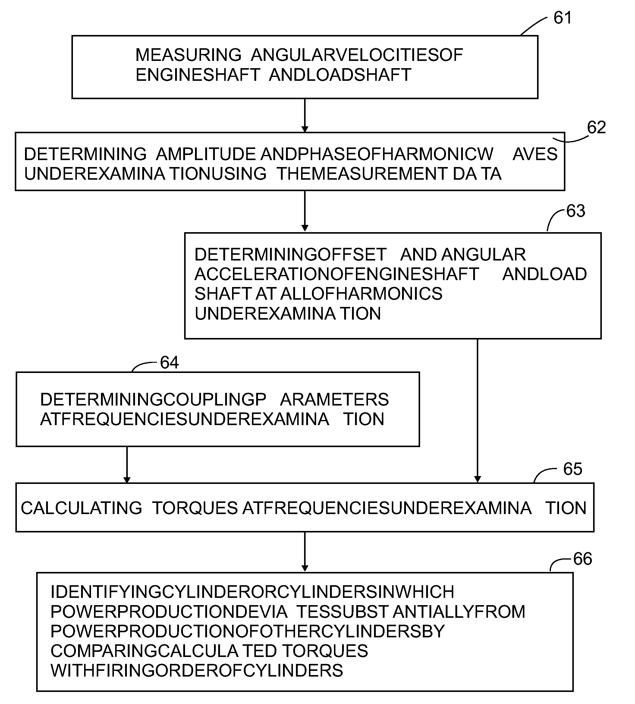
The invention provides a method and apparatus for detecting which cylinders in an internal combustion piston engine are producing harmful torsional vibrations on the shaft. This is done by measuring the angular velocity of the engine shaft and the load shaft, and calculating the torque output of each cylinder using the measured data. By identifying which cylinders are producing the most detrimental torsional vibrations, the invention allows for targeted maintenance or replacement of these cylinders to improve engine performance.

Problems solved by technology

Non-uniformity in power production due to differences between cylinders is manifested in all internal combustion piston engines.
Non-uniform shares of cylinder power cause torsional stress on the crankshaft of the engine and increase the level of engine vibrations.
Therefore the mechanical components of the engine are exposed to additional stress due to non-uniform power of the cylinders.
If the engine rotates in a RPM range in which detrimental torsional vibration is evident, the system delays the injection of fuel into the cylinders and sets a time limit for fuel injection.
The problem with these reference publications is that the efficiency of the engine's power production is hampered when torsional vibrations are damped.

Method used


Image

  • Apparatus for Identifying a Non-Uniform Share of Cylinder Power in an Internal Combustion Piston Engine System
  • Apparatus for Identifying a Non-Uniform Share of Cylinder Power in an Internal Combustion Piston Engine System
  • Apparatus for Identifying a Non-Uniform Share of Cylinder Power in an Internal Combustion Piston Engine System

Examples


Embodiment Construction

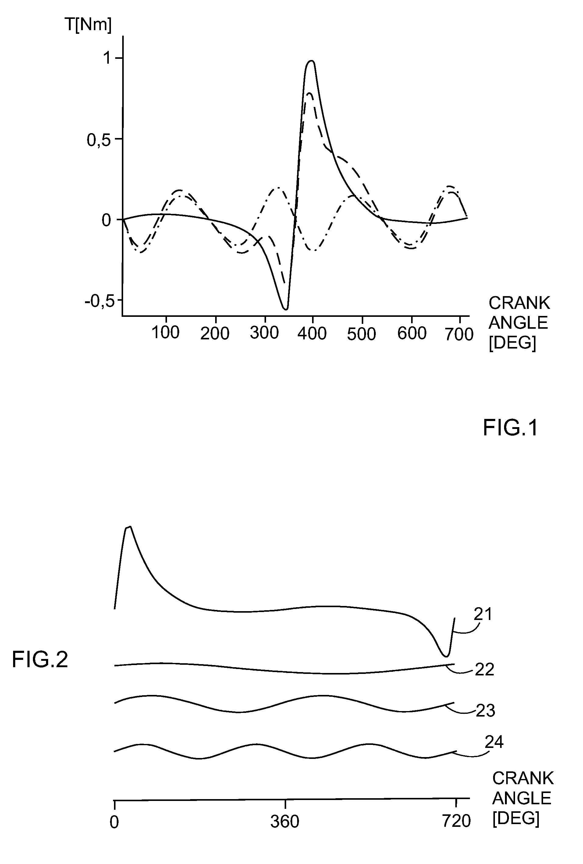
[0021]FIG. 1 illustrates an example of the torques of one cylinder in a four-stroke diesel engine, originating from the combustion of fuel and the rotation of mass. The gas torque is illustrated with a solid line, the mass torque with a dot-and-dash line and the tangential torque with a dashed line. The gas torque illustrates the torque originating from the combustion of fuel inside the cylinder. The mass torque originates from the reciprocating motion of the piston in the cylinder and the rotating movement of the crank mechanism. The tangential torque is the sum of the gas and mass torques effective on the engine's crankshaft. In a normal four-stroke multiple-cylinder internal combustion piston engine, the cycle of each cylinder takes two crankshaft rotations—that is, 720 degrees. It can be seen from the figure that the torque is at its highest during the power stroke and at its lowest during the compression stroke of the cylinder.

[0022]The torque curves of FIG. 1 are periodically ...


PUM


Abstract

The invention utilizes the firing order of the cylinders within the engine to identify the cylinder or cylinders that mainly contribute or, alternatively, contribute as little as possible to the production of certain harmonic frequencies in the engine's torque. In order to use the engine's torque for this purpose, the calculation of torque must take into account the non-linearities of the engine system. Thus the calculation of torque takes into account not only the properties of the engine but also the properties of the load and the shaft.

Description

FIELD OF TECHNOLOGY[0001]The present invention relates to an apparatus used in internal combustion piston engine systems on ships or in energy production. The apparatus is able to identify detrimental non-uniform power production of a cylinder or cylinders within an engine. The invention also relates to a method used in said apparatus.PRIOR ART[0002]Non-uniformity in power production due to differences between cylinders is manifested in all internal combustion piston engines. The differences are due to mechanical tolerances of the cylinders, mechanical and electromechanical tolerances of the fuel supply system, as well as other differences. Non-uniform shares of cylinder power cause torsional stress on the crankshaft of the engine and increase the level of engine vibrations. Therefore the mechanical components of the engine are exposed to additional stress due to non-uniform power of the cylinders.[0003]EP 447 697 presents a system for damping the torsional vibrations of a diesel en...

Claims


Application Information

Patent Timeline
Patent Type & Authority Applications(United States)
IPC IPC(8): G01M15/04F02DF02D41/00F02D41/02F02D41/14F02D41/34
CPCF02D41/008F02D41/021F02D41/1498G01M15/046F02D2041/288F02D2200/1004F02D2200/1012F02D2041/1432G01M15/11F02D41/14G01M15/04
Inventor OSTMAN, FREDRIK
Owner WARTSILA FINLAND OY
Learn More